|
DESIGNING WITH DIGITAL IC’S
All about logic gates, the basic building blocks of digital electronics.
JOSEPH J. CARR
Gages are the Fundamental building blocks of digital circuits. From the simplest devices to the most complex computers. Digital circuits are ultimately no more than collections of the basic gates described in this article. Those gates include the NOT, AND, OR and, EXCLUSIVE-OR. In addition, two other gates are con sidered basic, although they are essentially formed by marrying two other gates. Those are the NAND) (formed from a NOT and an AND) and the NOR (formed from a Nor and an OR).
Circuit symbols
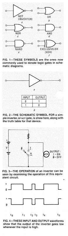
Over the years there have been several different sets of schematic symbols used for digital devices. As a result, at times, the industrial and military/aerospace segments of the electronics industry have had difficulty reading each others’ drawings. More recently. however, the set of symbols shown in Fig. 1 has become more or less accepted by all. Those are the symbols that we will use in the remainder of this series.
The NOT gate
The NOT gate, or inverter, is the simplest form of gate, and, indeed, some do not even consider it a gate. Figure 2-a shows the circuit symbol for that device, while its truth table is shown in Fig. 2b. The equivalent circuit for the inverter is shown in Fig. 3.
An inverter inverts. That is, its output signal is the complement of the input signal. as is shown in Fig. 4, and is always the opposite of the input.
In our equivalent circuit, the input state is indicated by the switch position. while the output state is indicated by the bulb. With the input low (switch open) the power supply is connected to the bulb through a current-limiting resistor, so the output is high (bulb on). But when the input is low (switch closed), the output is low (bulb off). Symbolically, if the input is A, the output is A, and if the input is A. the output is A.
There are several TTL and CMOS IC's that contain inverter stages. The most common form are hex inverters, which are integrated circuits that contain six independent inverters in one package. Examples of hex inverters include the 7404, 7405, 7406. 7407, 7416, and 7417. Of these, all but the 7404 use open-collector outputs.
At this point, it might be prudent to digress a little and mention non-inverting buffers. Those also, come in hex form (such as the 4050B). Those devices have fanout ratings of 10 and up, and do not invert the input signal. They are used to provide isolation between circuits and to increase the drive capacity of certain de vice outputs. Microprocessor outputs typically have fan-outs of 2, so they will not drive the heavily loaded lines normally found in personal computers. Devices with fan-outs to 100 are available.
An indication of the influence of personal computers is that IC manufacturers now offer octal buffers and inverters (de vices with eight independent buffers or inverters). Those devices match the 8-bit data bus typically used by many popular personal computers.
|
Copyright by Bill Bytheway, K7TTY February 2012