|
DC-TO-DC SWITCHING CONVERTER DAVID CONWAY
IN RECENT YEARS THE USE OF MICROPROCESSORS HAS BECOME common in many automotive applications. Because of the expanding flexibility that microprocessors offer, they are frequently implemented in cornputerized ignition and fuel injection systems, cruise control management, and engine monitoring.
Many microprocessors now operate from a single + 5 volts regulated power supply. Others may require in puts of + 12 volts, +5 volts, and —5 volts. Those voltages are uniquely different from the + 12 volts supplied by the automotive battery! alternator system and need to be converted to a more stable DC voltage source.
One way to convert + 12 volts supplied by the automotive electric al system to + 5 volts for single supply microprocessors would be to use a standard three-terminal IC power regulator. That method has two drawbacks. First, it would not be a feasible design to produce a —5-volt supply. Second, the three terminal regulator output is not isolated from transients and would require protective devices. Those devices usually consist of diodes, Zener diodes, filters, or decoupling schemes which enable the regulator to survive the extreme voltage transients that are generated when the engine is running and the alternator is charging the battery.
Most automotive charging systems produce transients in the order of 1 volt to 10-volts peak-to-peak. However, those transients may reach as high as 400- to 600-volts for several microseconds. Another type of transient produced by the charging system is a negative voltage (—50 volts) generated by self induction in the alternator field winding when the vehicle is turned off.
Those voltage transients cover a broad spectrum and are unique to each 12-volt automotive system They are dangerous to semiconductor devices and are responsible for “glitches”, fluctuating logic levels, false triggering, and resetting of registers, which result in invalid computation. In extreme cases those voltage transients could destroy the three terminal voltage regulator as well as the microprocessor and other supporting integrated circuits. A better way to isolate between the 12-volt automotive electrical charging system and the regulating circuit which supplies power to the microprocessor circuit could be achieved by use of the DC-to-DC Switching Converter. That novel power supply design provides three main functions: isolation, impedance transformation and voltage regulation. Isolation and impedance transformation are accomplished by a high frequency toroidal transformer. Regulation of the output voltages are maintained by pulse-width modulation. The drawbacks of the three-terminal IC power regulator circuit do not exist in this design. The voltage inputs of the IC power regulators are connected to the separate secondary circuits of the transformer, providing electrical isolation from transients.
Theory of operation
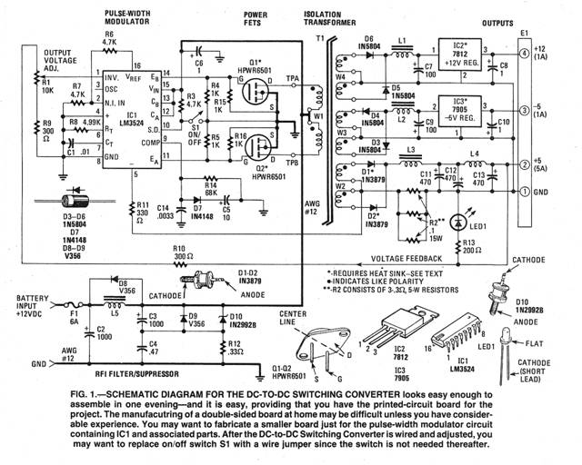
The DC-to-DC Switching Converter is wired in a push pull amplifier configuration comprising power MOS field effect transistors Q1 and Q2 which are driven by IC1, an LM3524 switching regulator IC, which provides pulse-width modulation control and drive signals for Q1 and Q2. See Fig. 1. The converter has complete over-current protection by sensing the current delivered by the + 5-volt regulated out put. The current is continually monitored by the current sense amplifier within the LM3524.
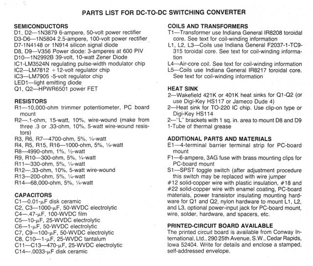
Outputs available from the converter are + 5 volts at 5 amperes, + 12 volts at 1 ampere and —5 volts at 1 ampere. The + 12-volt and — 5-volt outputs are obtained from IC power regulators IC2 and IC3 The advantages of IC power regulators may be safely obtained because of the isolation provided by the high-frequency toroidal transformer T1.
When using a microprocessor which only requires +5 volts as a single power requirement, the additional secondary windings W3 and W4 which supply power to voltage regulators IC2 and IC3 may be eliminated. The rectifier diodes, filter capacitors, and inductors, which support IC2 and IC3 are also eliminated completely from the circuit—further simplifying the power supply design. The +5 volts at 5-ampere output was chosen to be the main regulated output and is controlled by the LM3524 pulse width modulator IC1.
Regulation is maintained by a feedback loop, the + 5-volt output is connected to the inverting input of IC1 through potentiometer R1. The internal circuit of the LM3524 (IC!) is shown in Fig. 2. The output voltage of the + 5-volt output may be adjusted by R1. Paralleled resistor combination R2 limits the maximum output current to 6 amperes to provide component protection. Switch S1 is the power on/off switch for the unit. When S1 is open the shutdown pin on IC1 is forced high through R3, transistors Q1 and Q2 no longer receive their gate drive signals and high-frequency trans former T1 remains inoperative. Closing S1 allows IC1 to oscillate allowing Q1 and Q2 to drive T1 which supplies voltage to the output load. Power on is indicated by a green LED, which is connected to the regulated + 5-volt output.
Construction details
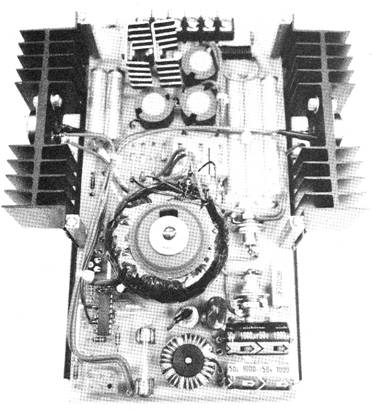
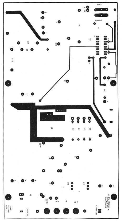
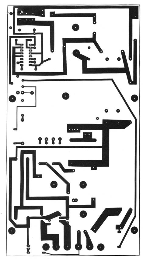
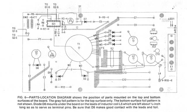
The circuit described may be built on a printed circuit board or vector board with point-to-point wiring. The circuitry should be housed in a metal enclosure to shield the radio frequency interference generated by Q1, Q2 and T1. Refer to Figs. 3, 4 and 6.
Whether using a printed-circuit board or point-to-point wiring, the power FETs Q1 and Q2 must be connected in the following manner: The source(s) leads of Q1 and Q2 should be grounded using AWG No. 12 wire. Resistors R15 and Rl6 should be soldered directly to the gate (G) and source(s) leads of Q1 and Q2. Resistors R4 and R5 are located on the PC board. Connections between IC1 and gates terminals of Q1 and Q2 should be as short as possible to prevent spurious oscillation from occurring on the gate drive signals. 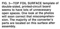
The drain leads of Q1 and Q2 should be connected directly to the
primary winding of
Transformer
The output transformer, T1, is constructed on a 2.4-inch diameter, toroidal transformer core. The toroidal core was chosen because of its simple winding properties while still maintaining high efficiency. Primary winding W1 is wound first and is made up of 23 bifilar turns using AWG No. 18 enamel-coated copper wire.
Secondary winding W2 is wound on the core next. This winding is made up of 18 bifilar turns of AWG No. 18 enamel-coated copper wire. Secondary winding W3 is made up of 22 bifilar turns AWG No. 18 enamel-coated copper wire. The last secondary winding, W4, consists of 50 bifilar turns using AWG No. 22 enamel-coated copper wire. When winding T1, turns should be spaced evenly around the core for all windings. Wrap a final layer of trans former tape over the core to secure the windings.
A word about the reason for bifilar windings used in the making of toroidal-core transformer T1: The author suggests that the builder wind both halves of the center-tapped windings at the same time so that in the event one more or less winding turn is accidently made, both halves of the center-tapped winding will have the same number of turns. As a bonus, with both halves of the winding wrapped side-by-side, the induced voltages in each half of the windings are more likely to be exactly equal. The solid dots near the ends of the windings of T1 in Fig. 1 indicate induced in-phase voltage relationships to all other windings, or like polarity.
Output inductors
The output inductors are wound as follows: L1, L2, L3 are identical. Wind 3½-turns of AWG No. 18 enamel coated copper wire through each core. The cores are secured to the PC board using nylon hardware. L4 is an air wound inductor. Wind close together 15 turns AWG No. 18 enamel-coated copper wire on a ¼-in, diameter form, then discard the form. L5 is made-up using 50 turns on more than one layer AWG No. 14 wire on a toroidal form.
Heat sinks
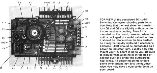
Voltage regulators IC2 and IC3 should be mounted on heat sinks. The TO-220 package of IC2 and IC3 allow clip-on heat sinks. Thermal compound should be applied between the regulator and the heat sink. Power rectifier diodes D1 and D2 also need to be mounted on a suitable heat sink which need be only "L" mounting brackets. Q1 and Q2 are packaged in a TO-3 case. Each power device (Q1 and Q2) should be mounted on a Wakefield 421K or 401K heat sink with thermal compound between neat sink and the TO-3 case. When the supply is used with loads which require maximum output current of all three voltage outputs, use Wakefield heat sink type 421K on transistors Q1 and Q2. Should you use an unknown-rated heat sink, compare physical size to known units, match and add a safety factor.
Power-up sequence
The wiring should be checked for accuracy, especially Q1 and Q2, and the polarity of diodes and capacitors.
Before power can be applied to the DC-to-DC Switching Converter, the switching operation of Q1 and Q2 needs to be checked. The best means of checking oscillation of IC1 is with an oscilloscope. Gate drive waveforms should be 180 degrees out-of-phase from each other and oscillating at ±25 kHz. However, if test equipment is not available, a simple visual test may be carried out to determine if Q1 and Q2 are switching properly. That test is carried out as follows:
Disconnect the drains of Q1 and Q2, and connect the test circuit shown in Fig. 5 to the drains labeled TPA (Test Point A) and TPB in Fig. 1. Parallel a 20 uF capacitor across C1. A 1 ampere, 12V regulated power supply should be connected to the + 12-volt battery input of the converter. The test circuit in Fig. 5 should also be connected to this + i2V supply. When S1 is turned on the LED’s in the test circuit should blink back and forth but should not be on simultaneously. If the LED’s are inoperative, check IC1, Q1 and Q2 for wiring errors. If the switching test is satisfactory, turn S1 off, remove the 20 uF capacitor which is paralleled across C1 and disconnect the test circuit from test points A and B, and reconnect the drain leads of Q1 and Q2 to primary winding W1 of transformer T1. The DC-to-DC Switching Converter is now ready to be tested.
Connect the ground lead of the DC-to-DC Switching Converter to a power supply capable of supplying at least 8 amperes at +12 VDC. A 5-ohm, 10watt resistor should be connected in series with the power supply ‘+ V out put and the converter battery 12-volt input. Connect a voltmeter across the + 5-volt output but do not connect any loads to the converter outputs. S1 should be turned on and the green power "on" LED should glow. Adjust R1 for a +5V output.
The supply may now be tested with a load. With S1 turned off connect a 1 ohm. 30-watt resistor across the +5-volt, 5 ampere output. The 20 ohm. 10-watt resistor may now be removed from the power supply and the converter input should be connected directly to the power supply supplying + 12 volts for testing. Turn S1 on and readjust R1 for +5V. When the converter is adjusted properly using the + 12V test supply, it should then be connected to the + 12-volt automotive electrical system. Minor adjustments of R1 may be necessary. When the unit is fully tested it may be connected to the microprocessor project.
Conclusion
The DC-to-DC Switching Converter will convert the +12-volt input to the regulated output voltage(s) required by a single or multiple supply microprocessor. The simplicity of the converter allows the possibility of additional output voltages than the ones discussed. T1 may be easily rewound scaling the number of turns to the desired output. When rewinding T1 for other output voltages R1, R8, and C1 values may need some experimentation. After any modification always following the same power-up sequence to avoid destruction of transistors Q1 and Q2. Isolation between the +12-volt automotive electrical system insures reliable operation of the microprocessor projects as they are not subjected to destructive transients associated with 12-volt automotive electrical systems. Additionally in areas where brown-outs are very common, the DC-to-DC Switching Converter can be operated off an unregulated 12 - 15-volt DC supply which is either line powered or line recharged.
|


Copyright by Bill Bytheway, K7TTY February 2012