|
Current Limiting Techniques
BY MARK PITTELKAU
How to protect power transistors from overload damage POWER supplies, like audio power amplifiers, are designed to deliver a selected maximum current to a load. If for any reason the load should draw more current than the supply can safely deliver, severe damage can occur.
To prevent this from happening, fuses are usually used at the input to the power supply. However, thermal lag and overrating to accommodate turn-on surges often allow damage to occur before the fuse link pops. To overcome this deficiency, more and more designers are turning to fast-acting current-limiting circuits.
In this approach, a circuit is incorporated within the power supply to allow only a preset amount of current to flow to the load. If excessive loading occurs, the circuit will automatically limit the current to a safe value. When the excessive drain is removed, the supply resumes normal operation.
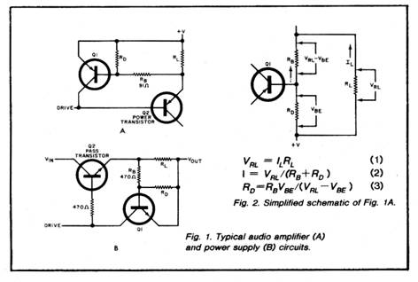
One commonly used technique, shown in Fig. 1 for both an audio amplifier (A) and a power supply (B), requires insertion of low-value resistance R1 in series with the load and power supply. In both cases, transistor Q1 (and its associated components) acts as a high-speed switch that controls base current to the power transistor.
Note that RL is connected between Q1’s emitter and base, with the Q1 collector connected to the base of the power transistor to be protected. When load current IL flows through RL the voltage generated across it is equal to ILRL. The load is selected so that when the desired maximum current flows, the developed voltage will turn Q1 on. When this occurs, QI will shunt the base drive to the power transistor and, in effect, hold it off for as long as load current demand is excessive. Current limiting occurs when the voltage drop across RL is equal to about 0.6V, the barrier potential of a silicon junction. Therefore, RL = 0.6/IL. The value of RL can be quite small and often will have an odd, difficult-to locate value.
To prevent Q1 from switching so rapidly that the circuit becomes unstable, parasitic-suppression resistor R3 is included in the current-limiting circuit. (If R8 does not exist in your circuit, you can add one having a value between 100 and 1000 ohms.) The presence of R8 also allows voltage-divider resistor RD to be added between the base and emitter of current-limiting transistor Q1. This in turn allows use of a higher resistance value for RL. The simplified schematic of Fig.1A shown in Fig.2 is similar to that of Fig.1B. except that IL flows in the opposite direction and an npn transistor is used for Q1 instead of pnp type. This does not affect the following computations since only magnitudes are be ing considered.
The following example illustrates one method for calculating the correct value for RD so that it will work with the value of the RL you have. Assume that IL = 3.3 amperes, RL is 0.18 ohm, and we have only a 0.27-ohm resistor on hand. The 0.27-ohm resistor will decrease the current limit to 2.2 amperes, but the addition of RD will increase the limit to any value within the capabilities of the pass transistor and the power source. At 3.3 amperes current flow (IL)’ the voltage (VRL) across the 0.27-ohm resistor can be calculated from VRL = IL RL (Eq. 1) which works out to 0.89 V.
Since control transistor Q1 is silicon, it will turn on when its base is biased at 0.6 volt (Vbe) This 0.6-volt must be dropped across R8 when 3.3 amperes flows through RL. Resistor RD must then drop VBE or 0.6 volt at this current flow. See Eq. 3.
Using Fig.1A as an example, RD = (91 X 0.6)/(0.89 — 0.6), or 188 ohms. Using Fig. 1 B as the example, RD works out close to 970 ohms. In either case, one would use the closest standard value, or a slightly lower value with a series trimmer potentiometer for “fine tuning” if desired. A half-watt rating will be sufficient. To calculate the current flow through the R8, RD network, use Eq.2.
To provide an optional variable cur rent
limit, a suitably valued potentiometer can be used for RD. However,
if this potentiometer is set to too low a resistance value,
excessive current can flow. For safety, insert a low-value
resistance in series with the RD potentiometer. The value of this
resistance should be selected so that slightly less than maximum
current flows when the potentiome
In Conclusion. The protective circuitry shown here may not work for a load that demands large, rapid changes in current, nor for wide-band width, high powered audio amplifiers that may feed highly reactive loads.
Difficulties may also arise if the pass transistor (Q2) operates very close to its maximum ratings or is driven from a three-terminal regulator. In the latter case, the sum of the current rating of Q1 and the current drawn by the base of Q2 at maximum output current must exceed the maximum current delivered by the regulator. In general, the circuit will work satisfactorily for moderate variations in load current that do not occur extremely rapidly.
|
 ter
is set to zero resistance. Be sure to use a resistor with sufficient
dissipation capacity for RL. Failure of this resistor may cause
serious damage elsewhere in the circuit.
ter
is set to zero resistance. Be sure to use a resistor with sufficient
dissipation capacity for RL. Failure of this resistor may cause
serious damage elsewhere in the circuit.Copyright by Bill Bytheway, K7TTY February 2012