|
Continuity Tester 1
Having good contacts is important – not only in
your daily life, but also in electronics. In contrast to social
contacts, the reliability of electrical contacts can be checked
quickly and easily. Various types of continuity testers are
commercially available for this purpose. Most multimeters also have
a continuity test function for electrical connections. A simple beep
helps you tell good contacts from bad ones.
However, in some cases the tester doesn’t produce a beep because it
won’t accept contact resistances that are somewhat higher than
usual. Also, poorly conducting (and thus bad) connections are
sometimes indicated to be good. Here e-trix comes to your aid with a
design for a DIY continuity tester that helps you separate the wheat
from the chaff.
Circuit diagram:
Continuity Tester Circuit Schematic
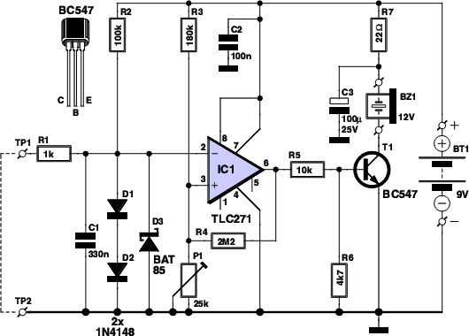
Circuit
description:
Many multimeters have a built-in continuity test function. However,
in many cases the resistance necessary to activate the beeper when
you are looking for bad connections is just a bit too high. It can
also happen that the beeper sounds even though the resistance of the
connection is unacceptably high. This circuit lets you adjust the
threshold between bad and good contacts to suit your needs. The
circuit is built around an operational amplifier (IC1) wired as a
comparator.
The opamp compares the voltage on its inverting input (pin 2) with
the voltage on its non-inverting input (pin 3). The voltage on pin 3
can be set using potentiometer P1, so you can set the threshold
between good and bad connections. When test probes TP1 and TP2 are
placed on either side of a connection or contact to be tested, a
voltage is generated across the probes by the current growing though
resistors R1 and R3, and it appears on pin 2 of the opamp. This
voltage depends on the resistance between the probe tips.
If the voltage on pin 2 is lower than the reference voltage on pin
3, the difference is amplified so strongly by the opamp that its
output (pin 6) is practically the same as the supply voltage. This
causes transistor T1 to conduct, which in turn causes DC buzzer BZ1
to sound. This means that the resistance of the connection being
tested is less than the threshold value set by P1, and thus that the
connection is OK.
By contrast, a bad connection will cause the relationship between
the voltages on the inputs of the opamp to be the opposite, with the
result that its output will be at ground level. The transistor will
not conduct, and the buzzer will remain still. To ensure that the
opamp ‘toggles’ properly (which means that its output goes to ground
level or the supply voltage level) when the difference voltage is
sufficiently large and does not oscillate during the transition
interval due to small fluctuations in the difference voltage
produced by interference, its output is coupled back to its
non-inverting input (pin 3) by resistor R4.
This causes any change on the output to be passed back to this input
in amplified form, with the result that the detected difference
voltage is amplified (and thus boosted). Diodes D1, D2 and D3
protect the circuit against excessive positive and negative input
voltages that may come from the connections or contacts being
tested. They also ensure that the continuity tester does not inject
excessively high voltages into the item under test. Capacitor C1
suppresses high-frequency interference. The circuit draws only a
small supply current, so it can easily be powered by a 9-V battery.
Source: Elektor Electronics 12-2010
|