|
Charge Indicator
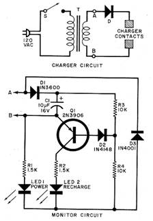
Keeping track of the operation of a cordless soldering iron’s recharging stand is the function of the circuit shown. The stock charger for a typical quickly rechargeable iron is labeled CHARGER CIRCUIT, while the supple mental indicator circuit is the MONITOR CIRCUIT. A simple half-wave dc supply comprising stepdown transformer T and diode D is the stock charger. Power switch S permits manual control over the flow of ac to the charger. This can prevent continuous application of charging current after the NiCd cells have been fully replenished—some thing that can shorten useful battery life. The charger circuit delivers pulses of charging current to the iron’s NiCd cells when the voltage between points A and B is positive enough to overcome the forward voltage drop of diode D and the voltage of the cells to be charged.
The monitor circuit does not affect the recharge rate at all. It functions as follows. Diode D3 conducts during the negative halfcycle of the power waveform, when point B is positive with respect to point A. Current flows through R1, LED1 and D3, causing the LED to glow. Light from the LED indicates that power is applied to the charger.
When an iron containing discharged batteries is placed in the stand, the voltage across the charger contacts decreases to approximately 3 volts. Capacitor C1 charges through D1, but only to a lower voltage level. This forward biases D2 and drives QI into conduction during the negative (noncharging) half-cycle of the ac waveform. This LED, like LED!, pulses on and off so fast that it appears to glow continuously.
Power for the two LEDs is derived from the charger during the noncharging halfcycle of the ac waveform, so the recharging rate is not affected. Only 0.4 mA or so is tak en from the charger circuit during the intervals when the NiCd cells are receiving pulses of charging current.
Scott A. Woods, Madison. WI.
|
Copyright by Bill Bytheway, K7TTY February 2012