|
CAR TEST PROBE
Simple instrument for on-the-spot electrical
system tr
G.J. BEARMAN
THIS USEFUL PROJECT WAS DESIGNED AS A PIECE OF simple test gear to be carried around in the car for on the-spot electrical system troubleshooting. It can be built in various forms to suit the individual requirements of the user.
The first part of the probe consists of two LED’s that indicate the condition at any electrical connection in the car. With the probe unattached, both LED’s light, indicating a voltage level that is neither positive nor negative. When the probe is applied to a connection with a definite voltage condition on it, the appropriate LED will light and the other will go out.
Voltage sensing
The second part of the probe consists of a voltage sensing circuit, using a 741 operational amplifier to detect when the voltage across the car battery rises above 12.5 volts. This provides a simple way to check that the battery is being charged.
It is obvious how LED 2 and LED 3 detect the voltage levels. They are connected in series with R4 and R5 as current-limiting resistors. When the probe is connected to either a positive or a negative voltage one or the other LED is effectively shorted, leaving just the other one on.
Comparator circuit
In the second part of the circuit, a 741 operational amplifier IC is used as a comparator. Its output state changes when the voltage on one input rises above the other input. A reference voltage is seen across Zener diode D1, by the input on pin 3, and pot R6 is used to set the required voltage on pin 2. When the battery voltage drops, the voltage on pin 2 will drop below that on pin 3, causing the output to go high and lighting LED 1 marked CHARGING.
Construction steps
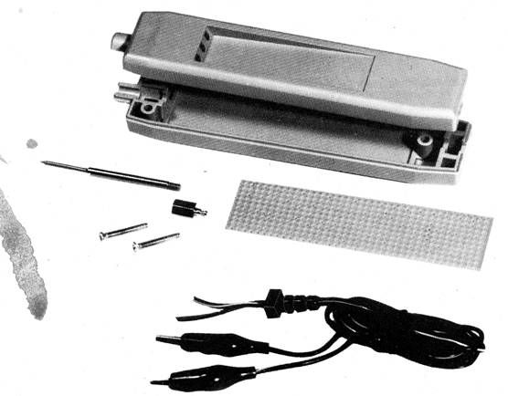
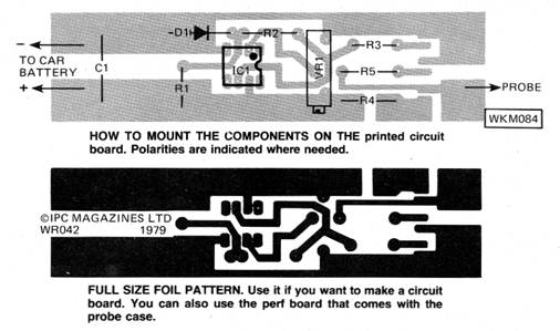
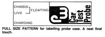
This printed-circuit board houses all the components including the three LED’s that fit into holes in the case. During assembly you must be certain that the LED’s and the 741 operational amplifier are positioned correctly. The small front panel can be cut out of the magazine or reproduced. Then it is carefully cemented onto the recessed portion of the case to give easy identification of the state being sensed by the probe.
PC board description
The printed-circuit board foil pattern is
reproduced full size as is the component placement drawing. The
photograph shows the probe case kit. If you use the circuit board
you will not need the perf board. How ever, you can use the perf
board and skip the printed circuit. Make sure that the LED’s are
correctly oriented. The “bridge” can be glued to the PCB using one
of the rapid bonding adhesives. Align it carefully, so that the
LED’s fit into their holes in the case top.
Testing the unit
After the circuit has been completely assembled it is tested by first setting R6 to the center of its range, and connecting a variable-voltage supply and a volt meter across C2. Now, with the unit turned on, when you reach a voltage somewhere between 6 and 12 volts LED1 comes on (or goes off). The preset is now adjusted so that the LED just goes out when the supply exceeds 12.5 volts.
Ignition timing
Keep the test probe in your car’s glove compartment or trunk. You will always have it ready for use in case of electrical problems. It can also be used to detect the instant at which the contact breakers open, enabling accurate static ignition timing to be carried out.
|
 oubleshooting.
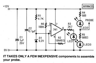
 The
probe is constructed onto a small printed-circuit board that fits
into a plastic probe case made by Global Specialties Corporation.
The
probe is constructed onto a small printed-circuit board that fits
into a plastic probe case made by Global Specialties Corporation.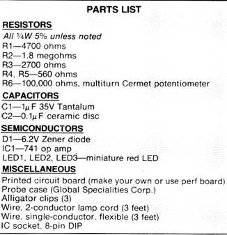
Copyright by Bill Bytheway, K7TTY February 2012