|
BROADCAST - OUALITY PHONO PREAMP
Variable equalization, low noise, and low distortion are just some of the features of this high-quality instrument.
THIS BROADCAST-QUALITY PHONO PREAMP IS A STATE of the art instrument in terms of performance and low noise. In addition it offers several new features not available in most commercial products.
Many phono preamps have three limitations. They are:
a. High output impedance
b. Fixed equalization
c. Gain irregularities
Let’s take a brief look at each of these problems.
Output impedance:
Broadcast requirements specify either 600- or 150-ohm balanced lines between electronic equipment. The reason for this is that low impedance lines are less susceptible to noise which permits running long distances without loss of fidelity. Most preamps on the market have unbalanced outputs with impedances of 4,000 — 10,000 ohms and therefore, are not capable of driving low-impedance lines. The preamp described below is capable of driving either 600 - or 150-ohm lines and provides for either balanced or unbalanced configurations.
Equalization:
All modern phonograph records are supposedly cut using the RIAA standard which was adopted in the early 1950’s. Yet there seems to be great variation in modern recordings even from a given recording company. These variations occur in the upper end of the frequency spectrum. On some recordings the highs overpower the rest of the spectrum resulting in a very shrill sound. On others the highs are suppressed resulting in a “tubby” sound reminiscent of the old 78 recordings. Most phono preamps provide only RIAA equalization. This limitation prevents proper equalization of signals during dubbing of records onto tape. The preamp described here provides a variable equalizer which includes the RIAA standard.
Gain:
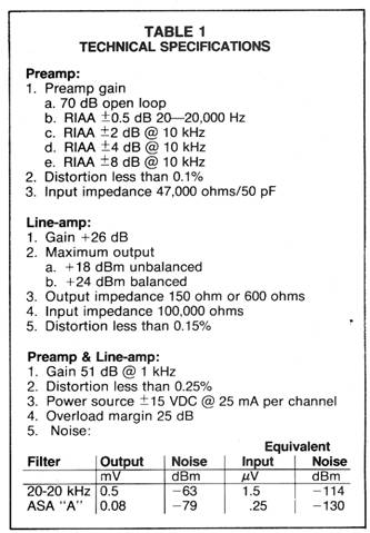
Most designs use a single-stage high-gain pre amp which can lead to problems at low frequencies. A preamp with a gain of 60 dB at 1 kHz requires a closed loop gain of 80 dB at 20 Hz and obviously a higher open-loop gain. This is difficult to achieve without design compromises. The design described below solves this problem by using a preamp with a gain of 34 dB and a line amplifier with a 26 dB gain. A trim pot between these two stages sets the overall gain to any desired level. This approach permits optimizing the preamp for low noise and low distortion while the line amp provides a low output impedance at any gain selected. The complete schematic is shown in Fig. 1. Specifications are giving in Table I.
The circuit is essentially divided into two parts: the preamp and the line-amp. The preamp is a classical transistor arrangement. Transistor Q1 was selected and biased for low noise, while Q2 and Q3 are tied in a Darlington configuration for high gain to prevent the loading of Q1. Resistors R2, R5, and R8 establish DC bias. Equalization is determined by the feedback loop consisting of R3, R4, C3, and C4. The value of C4 is selected by switch S1 to provide RIAA equalization with a variation of up to ±8 dB at 10 kHz.
Trim pot R9 which is used to set the output level is placed between the preamp and the line-amp. The out put of channels A and B can thus be set to exact and equal levels.
The LF357 operational amplifier was chosen for the line-amp because of its linearity, high slew-rate, and wide bandwidth. Transistors Q4 and Q5 were added to provide drive capability into 150 and 600-ohm loads. The line-amp uses direct coupling and is flat from DC to 200 kHz; C8 is used in the feedback 1oop to roll off the highs at 50 kHz, while trim pot R10 sets the DC level at the output to zero. For proper operation the line-amp must be terminated in a load of at least 600 ohms. The load resistor can be placed at either the line-amp or at the far end of the line.
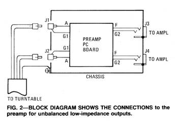
Figure 2 shows the connections for the unbalanced case. To provide a balanced line a high-quality transformer is required for each channel as shown in Fig. 3. This arrangement provides a balanced line of 150 or 600 ohms.
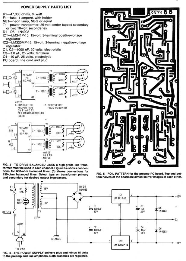
The power supply shown in Fig. 4 is simply a standard split supply with three terminal regulators yielding ±15 volts DC.
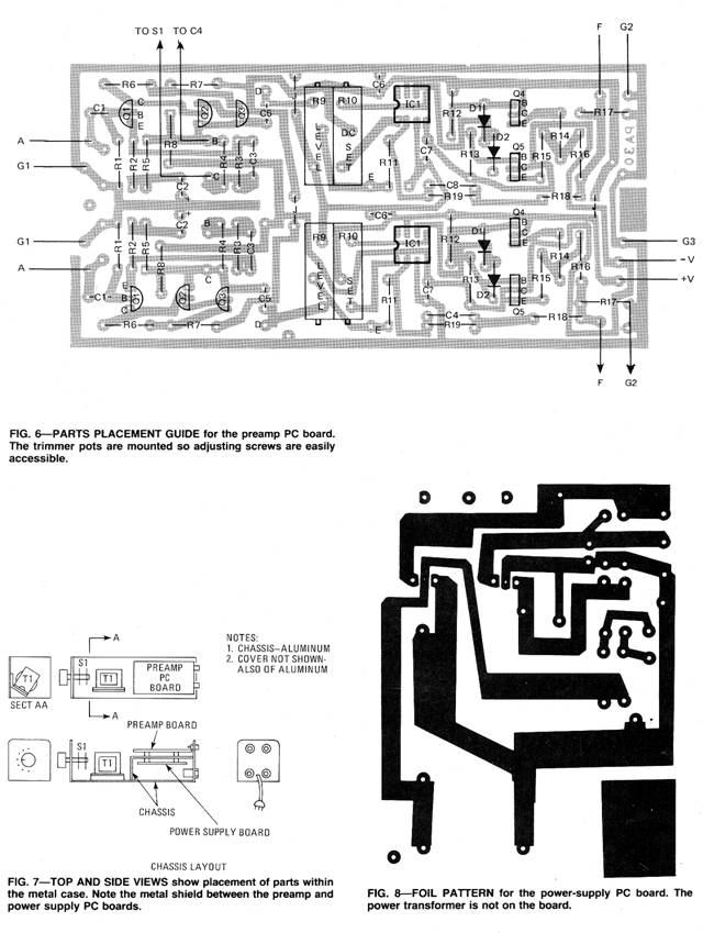
Construction
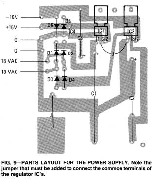
Two channels can be constructed on one printed circuit board. The foil pattern and parts layout are in Figs. 5 and 6, respectively. The PC board should be housed in a metal case to insure low noise. The power supply can be mounted in the same case with a metal shield between the power supply and the preamp. See Fig. 7.
Grounding is especially important in reducing noise. The ground system for the electronics should be tied to chassis only at one point. This is accomplished on the power supply.
The separation of electronic ground from the chassis imposes the following restrictions.
a. The phono cartridge return leads must not be tied to chassis.
b. The output ground lead must not be tied to chassis.
c. The turntable chassis must be tied to the PA-30 chassis.
These arrangements are shown in Figs. 2 and 3.
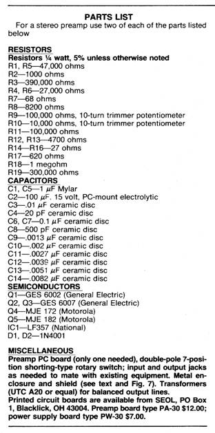
The power supply foil pattern are in Fig. 8 and the parts layout is shown in Fig. 9. Any residual hum can be totally eliminated by rotating the power transformer and moving its location on the chassis to an optimum position. A tested layout is shown in Fig. 7.
|
 Circuit description
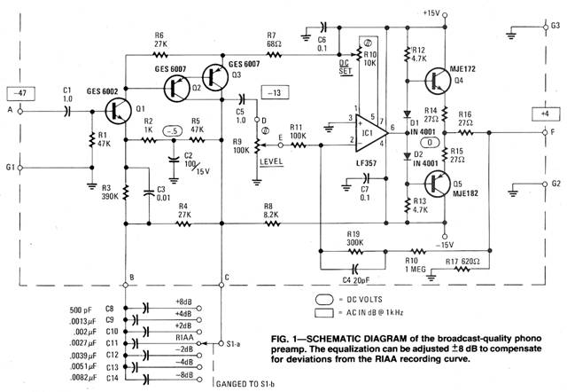
Copyright by Bill Bytheway, K7TTY February 2012