|
A BATTERY-OPERATED FLUORESCENT LAMP
Portable, high-efficiency light source draws current from a vehicle’s 12-volt storage battery, but leaves plenty of charge for engine starting.
BY LAWRENCE M. WALDEN
THE recreational vehicle is be coming more and more popular with campers who want a “home away from home.” In such cases, the vehicle’s 12-volt battery supply pro vides a convenient source of power for lighting around the camp. This is very handy, of course; but, for the amount of light they deliver, 12-volt incandescent lamps waste a lot of valuable battery power. Fluorescent lamps, on the other hand, produce good lighting at high efficiency. Unfortunately, they require a dc-to-ac converter.
The low-cost circuit described here not only performs the dc-to-ac conversion, it also provides automatic shutdown when the battery reaches some predetermined voltage level, thus pre venting a complete discharge. A LED indicator glows when the turnoff point is reached. Once turned off, the system draws only a few milliamperes.
Circuit Operation. When the 12 volt supply (Fig. 1) is applied to the circuit through fuse F1, switch S1. and the protective diode, D1 multivibrator IC1 starts to oscillate at a frequency determined by the setting of R2. This is approximately 10 kHz. At this time, Q1 is cut off to allow IC1 to oscillate.
As the + 12 volts are applied to the R18/zener diode D2 network, 7.6 volts are applied to the emitters of Q3 and Q4. At this time, the base of Q4 is at zero voltage, thus turning this transistor fully on and developing approximately 7 volts across its collector resistor (R12). This voltage, applied via R13 to the base of series-pass transistor Q5, turns the transistor on and allows the output of IC1 to pass through R7 to driver transistor Q6. The latter, in turn, drives power transistor Q7 to its maximum output.
The collector load of Q7 is formed by the 6.3-volt winding of transformer T1. Thus, as ICI oscillates, a high alternating voltage is developed across the 120-volt winding of TI and ap plied to the two series-connected fluorescent lamps (L1 and L2), and across current-sensing resistor RI 7.
At lamp turn on, the voltage developed across R17 is rectified and filtered by D3 and C5 and applied across lamp-current-adjust potentiometer Rl6. A preselected portion of this voltage is applied to the R15/C4 network and to the base of Q4. When this voltage approximates the 7.6-volt emitter reference, Q4 starts to reduce its conductance, thus lowering the voltage developed across collector resistor R12. This action lowers the bias on series-pass transistor Q5, reducing the drive to Q6/Q7 to lower the lamp drive and reduce the voltage across R17. The circuit stabilizes lamp current preset by R16.
At initial lamp turn on, approximately 1.3 amperes will flow through Q7 until the fluorescent lamps fire. This ensures lamp start even in cold weather. Once the lamps strike, the current will range from about 0.9 ampere at 13.2 volts to about 1.1 amperes when the battery voltage drops to near 10.6 volts.
Low battery protection is provided by potentiometer R6. The selected voltage is applied via R8 to the base of Q3. In normal operation, Q3 is cut off since its base voltage is higher than the 7.6 volts applied to its emitter. If the battery voltage drops so that the base of Q3 goes below the emitter voltage, Q3 starts to conduct and its collector current flows through R10 to the base of Q2. When Q2 starts to conduct, the base drive of Q3 is further reduced until both Q2 and Q3 are latched fully on. Once latched on, the collector of Q3 will be approximately 6 volts, which are applied through R11, causing LED1 the low-voltage indicator—to glow. This voltage is also applied via R5 to the base of Q1 to bias this transistor fully on. When this occurs, pins 2 and 3 of IC1 be come fully positive, thus disabling the multivibrator. At this point, battery consumption drops to about 50 mA, since Q1 Q2, and Q3 are the only active elements. Operating power should now be removed via S1.
Capacitor C4 at the base of Q4 is a high value to prevent oscillation, while C3 at the base of Q2 allows the circuit to stabilize before low voltage levels can be detected. Once the circuit is working, it responds very rapidly to voltage drops.
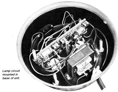
Construction. Since there is nothing critical about the circuit, it can be constructed on a small piece of perf board using point-to-point wiring and sockets for IC1 and the seven transistors. Transistor Q7, transformer T1, power on/off switch S1, fuse F1, and the two fluorescent lamp sockets are mounted on the enclosure.
Select an enclosure that can sup port the circuit board, the transformer, a heat sink for power transistor Q7, and the sockets for the two fluorescent lamps. The two lamps can be mounted vertically on top of the enclosure, and provided with some form of transparent weather protection such as a plastic sleeve. If a metal enclosure is used, it can serve as the Q7 heat sink when a suitable insulator is used. Connection to the + 12 volts can be made with a length of conventional two-conductor lamp cord having a cigarette lighter plug at one end. The author used 33 feet of lamp cord.
Since the secondary of transformer T1 can develop as much as 1500 volts peak-to-peak across the output, and as much as 225 volts when the lamps are lit, suitable insulation must be used at these points. Also, keep these voltages in mind when performing the adjustments on the circuit.
Adjustments. Before applying power, remove the connection between low-voltage-adjust potentiometer R6 rotor to the + 12-volt end. Then set lamp-current-adjust potentiometer R16 so that the rotor is at the ground end. Frequency-adjust potentiometer R2 should be set to the R1 side (highest resistance).
To make a complete test, use an adjustable power supply between 10 and 14 volts, with a capacity of at least 2 amperes. Connect an ammeter (about 2 amperes) in series with the positive battery connection, and a voltmeter (20-volt range) from the cathode side of D1 to ground. Connect the power source.
When SI is turned on, the lamps may not fire due to the low frequency of the multivibrator, and about 0.3 to 0.4 ampere will be drawn. Transformer T1 may also make sounds due to lamination movement, which indicates an operating circuit.
Slowly rotate frequency-adjust potentiometer R2 and note that the ammeter current increases and the lamps start to glow. Continue to increase the frequency very slowly until the lamps come to full brightness at a current of about 0.6 ampere. At this point, the supply current will suddenly jump to about 1.2 to 1.3 amperes. Advance the frequency for an additional 0.2 ampere, but not higher, as both output voltage and efficiency will drop.
If desired, the multivibrator can be “fine tuned” using an oscilloscope. To do this, turn the power off, set the controls as described above, remove the lamps and replace them with four 100 K ohm 1/2-W resistors connected in series. Connect the scope leads across R17, and set the scope vertical to 5 volts/division. Turn the power on and note that about 0.5 ampere flows and a 3 to 4 volt waveform appears on the scope. Slowly increase the frequency (via R2) until the scope trace peaks at about 15 volts peak-to-peak. The supply current should reach about 1 ampere at this point. Do not adjust the frequency higher than this, or the efficiency will be reduced. Turn the power off, remove the resistors, and replace the lamps.
To adjust the lamp current regulator with the lamps glowing, slowly rotate current-adjust potentiometer R16 until the current approaches 0.8 ampere and there is a decrease in light output. Then slowly adjust R16 until the current reaches 1 ampere. Lower the power supply to 10.6 volts, then re-adjust R16 for 1.1 amperes current flow. This becomes the maximum current drain at the lowest operating voltage.
Increase the supply voltage from 10.6 to 13.2 volts and note that the light output remains constant as the current decreases. With 12 volts applied, about 1 ampere will flow, and with a 13.2-volt supply, the current drops to about 0.9 ampere.
To adjust the low-voltage cutoff, reconnect R6 to the + 12-volt line and with the voltmeter still in the circuit, allow a 5-minute lamp warm-up. Reduce the power supply to 10.6 volts (or other desired low-voltage point) and slowly rotate R6 until the lamps go off and LED 1 glows. Recheck this point several times. If, during operation, the lamps go out, the presence of glowing LED 1 indicates that the low battery voltage has been reached, and the circuit has not been accidentally removed from the power source.
|

Copyright by Bill Bytheway, K7TTY February 2012