|
AN EARLY WARNING CAR BATTERY DRAIN INDICATOR
To avoid a dead battery, replace the standard “idiot” light with a visual-audible monitoring system
MESMAT replaces the ineffective “idiot” light, which will not light until the 12-V battery is discharging at a rate of 10 to 15 amperes. Consequently, a battery could be completely discharged while the car is running with out the standard warning light being activated. The project uses five LEDs to continuously monitor the condition of the vehicle’s electrical system, as well as a buzzer that sounds when voltage exceeds 16 to 17 V. (Excessive voltage might be caused by a defective voltage regulator, which could damage an alternator or other part of an electrical system.)
In addition to providing an early warning if a battery is being rapidly discharged, MESMAT audibly indicates when headlights are still on and the ignition is switched off. Further more, it can act as a continuity tester for checking fuses, bulbs, etc.
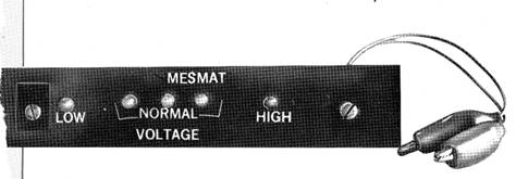
How It Works. MESMAT operates from a circuit board that mounts on the underside of the car’s instrument panel. Five LEDs light up in sequence as the voltage through the electrical system is increased. One or the other of three green LEDs will remain lit over the range of normal voltage. A yellow and a red LED on either end of the display light when the voltage is too low or high, respectively.
As shown in Fig. 1 MESMAT is built around two integrated circuits the LM3914 dot/bar graph display driver and the LM324N low-power quad operational amplifier.
In addition to a large network of voltage comparators, the LM3914 contains its own adjustable reference and accurate 10-step voltage divider. In MESMAT, the LM3914 is used in its dot-display mode and some of its outputs are connected together so that it drives four different LEDs instead of the normal 10.
As shown in Fig. 1, R1 is adjusted so that pin 6 of IC1 is 1.1 volts more positive than pin 4. (These pins are basically reference voltages.) The voltage (with respect to ground) at pin 6 determines the point when IC1's LED No. 10 output turns on (this out put sinks current when it turns on). The voltage at pin 4 plus 0.11 volt determines the point when IC1 turns on its LED No. 1 output. The other ICI outputs turn on at voltages between that at pin 4 and pin 6. The input at pin 5 is equal to approximately one-third that of the positive supply. Note that the positive supply is connected to the R15 / R5 voltage divider. When the voltage at pin 5 exceeds that at pin 4 plus 0.11 volt, IC1 turns on its LED No. 1 output. When the voltage at pin 5 exceeds that at pin 6, IC1 turns on its LED No. 10 output. The outputs at LED No. 2 through LED No. 9, of IC1, turn on when the voltage at pin 5 is somewhere between that at pin 4 and pin 6.
In this particular device, 10 different LEDs indicating 10 different volt age levels are unnecessary (and may actually be more confusing than helpful), so several of the outputs are connected to the cathode of a single LED. This is possible since IC1 uses open collector outputs. Since outputs on LED Nos. 1, 2, and 3 are all connected to the cathode of LED2, this LED is lit whenever these outputs are turned on. This occurs only when the applied vehicle voltage is between about 12 and 13.1 volts. IC1's LED No. 4 through LED No. 6 outputs are connected together so LED3 stays lit in the 13.1 to 14.2 volt range. The outputs on LED No. 7 through LED No. 9 are tied together, which means LED 4 stays lit in the 14.2 – to - 15.3-volt range. The LED No. 10 output is connected to the cathode of LED 5, which lights when the supply voltage exceeds about 15.3 volts. The LM3914 has a small amount of over-lap between segments to ensure that all LEDs are not off at once.
Op amps IC2A, JC2B, and IC2D are used as voltage comparators. The noninverting input of IC2a is connected to pin 4 of IC1 and its inverting input to voltage divider R11/R12. The inverting input of IC2a is at a potential slightly less than one-third that of the supply. Trimmer R11 is adjusted so that LED! (which alerts the driver to the presence of an abnormally low voltage in the electrical system), just lights when the supply voltage drops below the value that turns on LED 2, which is about 12 volts. This is the same point at which the potential at the inverting input of IC2a drops below the potential at pin 4 of IC1. Notice that the R11 / R12 voltage divider is required since, if the inverting input of IC2a were connected directly to pin 5 of IC1 (which, at first glance, would seem the thing to do), IC2a wouldn’t turn on until the supply voltage dropped below 11.67 volts. Also remember that IC1's LED No. 1 output doesn’t turn on until the supply voltage exceeds approximately 12 volts. The output of IC2b is connected, through D1 to the noninverting input of IC2C, which functions as a buffer. The output of IC2C is connected to the base of Q1, which drives alarm A1. Transistor Q1 also reduces the loading on IC2C, which could cause instability.
Power for IC2, through D4 and D5 is from two different sources — the radio accessory connection at the vehicle fuse block which leads to point A on the circuit board, and a headlight dimmer switch connection which leads to point B. The radio accessory connection is “hot” only when the ignition switch is on, and the dimmer switch connection is hot only when the headlights are on. Thus, IC2 is powered when either (or both) the ignition switch or the headlights are on. Due to R9 and R10, IC2D’s noninverting input has a potential of one-half the battery voltage when the headlights are on, and 0 volt when they are off. The inverting input to IC2D is equal to the battery voltage when the ignition switch is on and is at zero other wise. Thus, when the headlights are on but the ignition is off, IC2D switches on, which, in turn (through D2. IC2C, and Q1), turns on the alarm.
The theory behind the operation of the audible continuity tester portion of MESMAT is simple. When a sufficiently low resistance exists between points T1 and T2, the positive voltage from T1 is applied to pin 5 of buffer IC2C through D3. The buffer, in turn, provides a current to the base of Q1, which then provides sufficient current to operate .41. Fuse F1 maintains the auto’s electrical system reliability and zener diode D6 increases MESMAT’s reliability.
Construction.
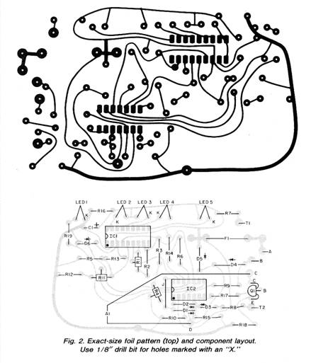
The circuit can be assembled on a pc board such as that shown in Fig. 2. Connect A1’s black (negative) lead to point C on the circuit board and its red (positive) lead to point D. For use as an audible continuity tester, connect short lengths of flexible wire, with an alligator clip at one end, to points T1 and T2 on the circuit board.
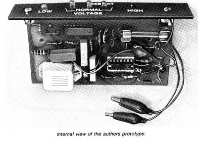
While the circuit board can be mounted in any small enclosure, the prototype had only a colored acrylic front panel, with the bulk of the circuit board exposed. Holes in the front panel were drilled for the LEDs, and two small right-angle brackets were used to attach the front panel to the circuit board. The front panel is used only for cosmetic reasons, as the circuit board can be mounted to the auto’s instrument panel.
Before applying power, check polarities of the LEDs, diodes, buzzer, and capacitor. Also, check to make sure you have installed the ICs and transistor properly.
Testing and Adjustment.
A dc power supply, continuously adjustable from 0 to 18 volts or more, and a dc voltmeter are required. (The current requirements of the supply are less than 50 mA.) Set trimmer pots (R1, R4, and R11) to their approximate midpoint. Connect the power supply’s ground to the circuit ground and the supply’s positive terminal to point A on the circuit board.
Set the voltmeter to measure 1.2 volts and connect its negative lead to pin 4 of ICI and positive lead to pin 6. Adjust R1 for a 1.1-volt meter indication. Then set the voltmeter so it will be able to measure 20 volts and connect its negative lead to ground and its positive lead to point A. Adjust the power supply until the meter indicates 12.0 volts, and adjust R4 until LED2 just barely goes off. (Make sure that LED3 doesn’t glow when LED2 is not illuminated.)
For the final adjustment, leave the power supply set at 12.0 volts and adjust R11 so that the yellow LED just barely glows.
To check the adjustments, set the power supply at 5 volts, and note that LED1 (yellow) starts to glow, and remains on to 11 volts. At 12.2 volts, LED2 (green) should be lit but LED1 should go off. (Note: As long as the voltage is over 5 volts, at least one of the LEDs should be lit at all times.) As the voltage is increased to 13.3 volts, LED2 should be off and LED3 (green) should glow. At 14.4 volts, only LED4 (green) should glow. At 15.5 volts, LED5 (red) should glow. As the voltage is increased over 17 volts, LED5 should still be lit but the alarm will sound. If necessary, read just R1, R4 and/or R11. Note that, if you desire the alarm to sound off at a specific voltage of your choosing, re place R14 with a 50,000-ohm potentiometer and adjust it so the alarm sounds off at your specified voltage.
To check the headlight-on reminder circuit, set the supply to 12 volts and disconnect the power supply’s positive supply lead from point A on the circuit board and connect it to point B. The alarm should sound off. Temporarily connect a jumper wire from point A to point B. The alarm should immediately be silenced.
To check out the optional continuity tester, short the two alligator clips (T1 and T2) together. The alarm should sound off immediately. Be sure you remove the temporary jumper between points A and B before installation in the vehicle.
Installation. The circuit board is designed to be mounted, foil side up, to the underside of the auto’s instrument panel. Use two suitable screws (sheet metal screws will usually work) and two nonconducting thick washers or short spacers. Other types of mounting, including recess, can be used with slight modifications. Although the author’s prototype doesn’t have a cabinet all that is really visible to the driver is the front panel.
After you have attached the project to the instrument panel, connect a wire from its ground connection to the auto’s ground. A nearby screw which threads into a metal chassis or body part is usually satisfactory. Next, connect a wire from point A to the auto’s radio or accessory connection at the fuse block. (A connection can be made at the fuse block without soldering by bending a thin solder lug into a semicircle and squeezing it between the fuse and fuseholder.) Use your VOM to make sure this connection is only “hot” when the ignition switch is “on.” Note: Whenever you make a connection to a fuse block, always check that the connection is made to the “protected” side—the side that is “dead” when the fuse is removed.
Connect point B on the circuit board to a connection at the dimmer switch that is “hot” whenever the headlight switch is “on.” The position of the dimmer switch shouldn’t matter. If you are on the ultra-cautious side, add a 1/4-amp in-line fuse in series with the wire to point B on the circuit board.
If you don’t like to see the continuity tester’s leads dangle when they aren’t in use, simply clip the alligators to the bottom of the front panel.
Use.
When the voltage of the electrical system is within normal limits (about 12 to 15 volts) one of the green LEDs will glow. Sometimes two LEDs glow at one time, but usually, the center or right green LED will be glowing. Under a heavy electrical load (as happens when the headlights, wipers, fan and electrical defrost are on at the same time) the left green LED may be the only one on. If the yellow LED glows for any extended time, the battery is being discharged and you most likely have some trouble with the alternator or battery. Another possibility is that there is an excessive load due to some short or a malfunction in an electrical part.
When there is little electrical load, it is usually OK for the right green LED and red LED to glow at the same time. However, if the red LED alone stays on for an extended time, you may have voltage-regulator problems. (Immediately after some cold weather starts, the red LED may glow for a few minutes. This is OK.) If the red LED comes on and the alarm sounds off, the voltage in the electrical system of the auto exceeds approximately 16.5 volts, which can cause a multitude of problems with the electrical system—ruined battery, short headlight life, and blown fuses. The difficulty should be determined and repaired as soon as possible.
The headlight-on reminder causes the alarm to sound off if you leave the headlights on and turn the ignition switch off. If you wish to operate the headlights with the engine off and not listen to the alarm, place the ignition switch in the accessory position.
The built-in audible continuity tester can be used to check questionable fuses and bulbs. Simply touch the alligator clips to the appropriate contacts on the fuse or bulb. If the alarm sounds, the part is OK.
In addition to being a worthy accessory for an automobile, MESMAT can be useful in a boat or any other vehicle that uses a 12-V battery.
|
 Like
the common cold, the “dead battery” syndrome seems to be especially
prevalent in the winter. This project, the Multipurpose Electrical
System Monitor And Tester (MESMAT), may help your car avoid the
dreaded ailment.
Like
the common cold, the “dead battery” syndrome seems to be especially
prevalent in the winter. This project, the Multipurpose Electrical
System Monitor And Tester (MESMAT), may help your car avoid the
dreaded ailment.
Copyright by Bill Bytheway, K7TTY February 2012