|
Automotive Voltage Regulator
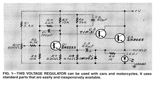
The circuit shown in Fig. 1 is the voltage regulator I’ve been using in both my car and the bike. It’s been working in my car for about eight years and I’ve never had any trouble with it. As you can see, it uses standard parts that can be gotten almost anywhere.
Before you go out and get everything you need to build the circuit there are some things you have to know about an alternator. Different bike and car manufacturers use different techniques to handle all the alternator connections and you have to know how your bike is set up before you get started. Since you’re rebuilding everything anyway, it may be possible to set things up in a manner different than what was done originally by the manufacturer.
Even though an alternator produces three-phase AC, as far as the external world is concerned it’s a DC machine. There are usually six diodes on two D-ring heat sinks that rectify the AC before it leaves the alternator. What sets an alternator apart from a generator is not only the need to rectify the output of the windings (a generator will produce DC directly), but also the presence of the field coil.
Alternators have a working similarity to transformers. You can think of the main three-phase windings as the secondary and the field windings as the primary. Like a transformer, the more voltage you have across the primary the more you’ll get out of the secondary. A voltage regulator for an alternator is essentially a controller that monitors the system voltage and tries to keep it at a certain level by adjusting the amount of current (and hence the voltage) present in the field windings.
Given all that, a standard alternator has four terminals that have to be connected to the electrical system. The secondary windings (the main alternator windings) are usually sent to power and ground, but the connections made to the field windings vary with the manufacturer of the car or bike.
The field terminals can be treated in one of the following ways: Both field terminals can be brought out of the alternator and left floating for you to connect any way you want, one side can be grounded inside the alternator (called a grounded field), or one side can be tied to the DC positive inside the alternator (called a pulled up field).
The schematic in Fig. 1 is designed to work with a system that has a grounded field. Since you’ve been fooling around with your own de signs, you should be able to easily modify it to work with a pulled-up field if that’s the situation in your bike. Basically, the voltage regulator monitors the system voltage and controls the field current by modulating Q2 and Q3 (they’re set up as a Darlington pair because I found it difficult to get the Darlington I wanted to use). The output is being modulated and the transistors are being run saturated (used as a switch) because they run a lot cooler that way.
The three external connections are + V (connected to the battery), the field (connected to the free end of the field coil), and ground (connected to system ground). Let me repeat that this regulator is designed to work in a system that has a negative ground and in which one side of the field windings is grounded as well. If your system is set up for a pulled up field and you use this circuit, you’ll blow up the regulator and possibly destroy some other electrical stuff in the bike as well.
As I said, I’ve been using this regulator in both my car and bike without any problem at all. I included LED1 in the circuit because it gives me a visual indication that the charging system (or at least the regulator) is working. You can use the potentiometer to adjust the knee of the regulator.
The setting here will determine what the steady-state voltage of the regulator will be. Moving it to one end will effectively turn off the charging system (although why you’d want to do that is beyond me), and turning it to the other extreme will cause the alternator to put out a lot of juice. That can be handy for those times when your battery is either in need of a charge or you’re putting a heavy cur rent demand on the electrical system (lights on in stop-and-go traffic during a heat wave and rainstorm). If you’re using the regulator in a car, you can mount the potentiometer and LED in side the car so you can monitor its action and make adjustments while you’re driving. The regulator should work well regardless of the construction method you use. I designed a PC board for it and, if you’re interested, drop me a line and I’ll send you a copy of the foil pattern.
|
Copyright by Bill Bytheway, K7TTY February 2012