|
Automotive Headlights Minder
Because this minor tragedy has happened to me once too often, I decided to end this headache by designing an automatic head light circuit—the Electronic Lightmaster. It waits patiently every time I switch off my car’s ignition, looking to see whether or not I’ve also switched off the headlights. If I haven’t, after a reasonable length of time (about 20 seconds), it simply switches them off for me . . . no ifs, ands, or buts.
Electronic Lightmaster is an apt name, because at the flip of a switch I can convert the circuit into a time-delay relay that purposely keeps my headlights turned on for about 2½ minutes after I leave my car. This feature transforms my car’s lights into mobile street lights that can illuminate dark driveways or paths during the short time it takes me to walk from my car to a doorway or some other entrance.
In the Works.
The circuit is built around a Darlington amplifier. This is a two-transistor design that has the very high input resistance needed to build a time-delay relay. Essentially, the amplifier looks at the voltage stored in capacitor C1 and applies almost the same voltage to the coil of relay K1.
To achieve the lighting effects we want, the circuit is connected to your car’s electrical system in an unusual fashion. To begin with, one of K1’s pair of contacts is wired in series with the headlight power line. Your lights will only work if K1 is activated, keeping the contact closed.
With switch S1 in its NORMAL position, the amplifier circuit is powered by the head light power line. Thus, when you flip your car’s light switch on, power is applied to the circuit. However, the relay will close only if capacitor C1 is charged to +12 VDC. Note that C1 is charged by a wire connected to your car’s ignition switch. This means that if you flip your light switch on and also have turned on the ignition, then your headlights will light up.
If for any reason you should turn off the ignition, capacitor C1 is no longer connected to a source of voltage. It will begin to discharge through resistor R2. As a result, its stored voltage drops, bringing along with it the voltage applied to relay K1. After 20 seconds, the voltage at the relay’s coil is too low to keep the relay activated and it drops out, thereby switching off the headlights.
Switch S3 is the system’s power switch — I’ve labeled it BYPASS. One pair of its contacts is wired in series with the relay coil, the other across the relay contacts that control the headlights. If you flip S3 to BYPASS, the circuit is effectively removed from the headlight wiring.
Building It.
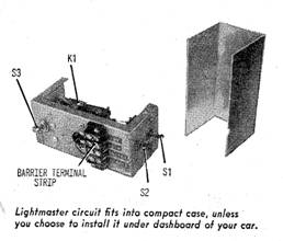
As with any automotive project, it’s difficult to design a single device that will fit into every car. So you may choose to use your ingenuity when you build the device and assemble it in a different kind of box. If you wish, you can even mount the guts underneath the hood and the three control switches on the instrument panel.
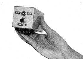
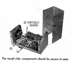
I wired the circuit into a 2½ x 2½ x 5-in, aluminum chassis box and hung it below the dash. My aim was to put the controls within easy reach. Parts placement isn’t critical. But since anything installed in a car will be shaken up a bit, be sure that all connections are mechanically and electrically sound.
To make the most of the limited space, I mounted the relay above the bottom of the case by placing spacers on its mounting screws. All wiring is clone in point-to-point fashion, using terminal strips as soldering and mounting points. To guard against short circuits, you should place sleeving on all leads that might conceivably brush against other wires or metal objects. This is important because the case is grounded and part of the electrical circuit.
Double check the polarity of C1 when you install it. The circuit won’t work if its leads are reversed.
Transistor Q2 is a newly-developed, plastic-encapsulated power transistor. Cut off the unused collector lead (the lead next to the beveled edge), and make all collector connections to the metal tab. This tab acts like a small heat sink and must be positioned clear of other components.
Bring the four leads that connect to your car’s wiring out to the four-terminal barrier strip. Use heavy duty wiring for these connections.
Installation
All required connections to your car’s wiring are outlined in our diagram. The only tricky area is the head light power line (it may take a while to find the correct lead). A wiring diagram for your car will be helpful, so try and get a copy (your public library may have a copy of the shop manual). The lead you want is between the master light switch and the hi/low beam switch. This single wire carries the power to light your headlights.
|
 What
can you say on a bleak morning when you discover that you
accidentally left your car’s headlights turned on the night before,
and your battery is now stone cold dead?
What
can you say on a bleak morning when you discover that you
accidentally left your car’s headlights turned on the night before,
and your battery is now stone cold dead?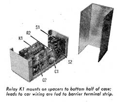
 When
you move S2 to its DELAY position, the Electronic Lightmaster is
modified slightly. Now R2 is removed from the circuit, so that the
only resistance which can discharge C1 is the very large input
resistance of the amplifier itself.
When
you move S2 to its DELAY position, the Electronic Lightmaster is
modified slightly. Now R2 is removed from the circuit, so that the
only resistance which can discharge C1 is the very large input
resistance of the amplifier itself. 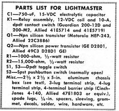 Practically
speaking, this means that it now takes 2½ minutes for the relay
voltage to fall low enough to deactivate the contacts. Also, K1’s
pair of contacts is placed across your car’s headlight switch. This
means that you can turn off the switch as usual when you leave the
car without disrupting the Lightmaster circuit. Pushbutton switch S2
brings capacitor C1’s voltage up to its full value when it is
pressed. Therefore, it functions as a RESET button. You need to use
it only on those occasions when you have already used up a good part
of the time delay before you’ve left your car. For instance, say you
take some time retrieving a lost item under your seat after you’ve
switched the ignition off. Pushing S2 for a full second restores the
time delay period.
Practically
speaking, this means that it now takes 2½ minutes for the relay
voltage to fall low enough to deactivate the contacts. Also, K1’s
pair of contacts is placed across your car’s headlight switch. This
means that you can turn off the switch as usual when you leave the
car without disrupting the Lightmaster circuit. Pushbutton switch S2
brings capacitor C1’s voltage up to its full value when it is
pressed. Therefore, it functions as a RESET button. You need to use
it only on those occasions when you have already used up a good part
of the time delay before you’ve left your car. For instance, say you
take some time retrieving a lost item under your seat after you’ve
switched the ignition off. Pushing S2 for a full second restores the
time delay period.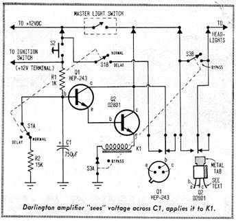
Copyright by Bill Bytheway, K7TTY February 2012