|
Solid-state vacuum gauge monitors gas consumption and driving habits
Poor driving habits can reduce fuel economy
by up to 50% regard less of how well-tuned and maintained the
vehicle. In the era of high-cost energy and shortages, you want to
get as much as possible from every drop of fuel your car bums. One
good way to do this is by using a device such as the Econometer
described here. It constantly and accurately monitors the relative
fuel consumption of your car so that you can adjust your driving
technique accordingly.
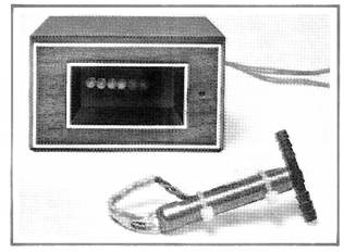
The Econometer is an electronic de vice that keeps tabs on intake-manifold vacuum. It has a display consisting of a row of eight LEDs. At idle, four or five LEDs normally glow. With your vehicle in motion, more or fewer LEDs glow, the maximum number (high vacuum) corresponding to high engine rpm and a small throttle opening and the minimum indicating low rpm and open throttle. High vacuum conditions give maximum fuel economy.
You will not be able to maintain high vacuum under all driving conditions. Naturally, accelerating from a standing start, driving up a steep grade, or hauling a heavy load all take more fuel than cruising on a level surface with a light load. But by observing the Econometer, you will be able to avoid using more throttle than necessary for any conditions, thereby saving fuel.
About the Circuit.
The simple circuit of the Econometer is shown schematically in Fig. 1. The vacuum transducer, a proprietary device manufactured by Alpha Electronics, receives power from 5-volt regulator IC2 through current limiting resistor R1. The output signal from the transducer is developed across R2, which is also connected to the stable 5-volt source.
The transducer mounts in the vacuum line from the carburetor. Its electrical output across R2 varies from 0.3 to 1 volt, depending on instantaneous manifold pressure. This voltage is applied to 10-step analog detector IC1.
The new integrated circuit used for IC1 contains 10 comparators and a reference-voltage network that detects the level of the analog signal at the input. Each comparator drives an open collector transistor that is capable of sinking 40 mA at S2 volts. Since the comparators are arranged in a “totem pole,” as input signal level increases, the LEDs light in succession. Potentiometer R3 provides a means for setting the operating thresholds.
Construction.
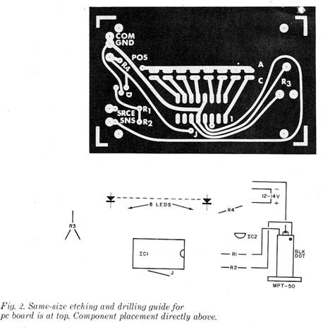
Because of the simplicity and noncritical demands of the circuit, any convenient board-type method of assembly—Wire Wrap, point-to-point on perforated board, or printed circuit board—can be used. An actual-size etching-and-drilling guide for a pc board is shown in Fig. 2.
Mount the LEDs with their tops flush and their bottoms about 1/4” (6.2 mm) above the surface of the board, carefully observing polarity during installation. Then install the single jumper and two ICs, again taking care to properly orient them. Use of a socket for IC1 is optional, but if you do use a socket, try to find a means of securing the IC (a daub of silicone rubber cement will do) so it will not vibrate loose.
Before mounting it in an enclosure, test the circuit board assembly. To do this, temporarily connect a jumper wire between the SNS (sense) point and GND (ground) in the circuit, apply 12 volts dc to the circuit, and check for a 5-volt dc reading between the junction formed by R1 and R2 and the ground bus. With R3 fully clockwise, all LEDs should light; turning the pot fully counter clockwise should extinguish all LEDs. Disconnect the dc power and remove the temporary jumper from the circuit.
Temporarily mount the circuit-board assembly in the enclosure in which it is to be housed. Carefully determine and mark the locations of the display and adjustment slot of R3 on the enclosure. Remove and temporarily set aside the circuit assembly. Then cut the display window slot and drill a screwdriver access hole for R3. Drill another hole through the side or rear of the enclosure to provide entry for the wires that will interconnect the circuit with its transducer and the vehicle’s electrical system. Deburr all holes and glue a red plastic filter over the display window. Line the wire-entry hole with a rubber grommet if you are using a metal enclosure.
Installation.
Five well-insulated color coded wires, preferably 18-gauge stranded, are required to interconnect the Econometer with its transducer and the vehicle’s electrical system. Lengths of the wires are determined by the mounting location of the Econometer where it will be easily visible at a glance and the location of the engine’s vacuum hose. Starting from where the Econometer will be positioned and leaving several extra inches, route a black insulated wire to a metal chassis connection or screw that is at chassis ground. Repeat this procedure with a red-insulated wire, this time terminating it at a source of fused + 12 volts that is “live” only when the ignition is on. Connect and solder the free ends of the black and red wires to the GND and POS pads, respectively, on the circuit-board assembly. Identify on your schematic diagram the colors used for each function for future reference.
Locate a source of intake-manifold vacuum (usually a rubber hose near or on the carburetor) so that the transducer and its leads will not be near a moving part or engine heat. Using this as your reference point, route three wires with different color insulation (not red or black) back along the chassis, through the firewall, and into the passenger compartment under the dashboard. Continue routing to the Econometer’s case location, leaving several inches of slack at both ends of the wires before cutting to final length.
Now, working with only one wire at a time, strip away 1/4” of insulation from the first selected, slip on a 3/4” (19-mm) length of insulated tubing, and solder the wire to the terminal closest to the black dot on the transducer. Solder the other end of this same wire to the SNS pad on the circuit board.
Remove 3/4” of insulation from the second selected wire and connect and solder it to both center lugs on the transducer. Solder the other end of this wire to the GND pad on the board. Then, prepare the last wire in the same manner as for the first, including the insulated tubing, and solder it at one end to the remaining lug on the transducer (push the tubing down over both connections) and to the SRCE pad on the circuit board at the other end. Indicate your wire colors on your schematic.
Bend the three-wire cable over the side of the transducer’s case, taking care to avoid obstructing the small hole in the case, and secure with a cable tie. Now, cut the vacuum hose and install the transducer in series with the cut ends. (You can install the transducer in either direction.) After installation, make sure the connections to the transducer are airtight.
Position the three-wire cable so that it and the transducer do not contact any moving parts and are away from engine heat. Bundle the cable conductors together with cable ties and secure the assembly to the vehicle’s chassis. Then assemble the project’s enclosure.
Checkout and Calibration.
Start your vehicle’s engine and allow it to idle in neutral. Using a small screwdriver, adjust R3, through the small hole in the front of the enclosure, until four or five LEDs are on. Still in neutral, slowly press the accelerator and note that the display changes by one LED. Release and then quickly press and release the accelerator. At first, only one LED should be on for a second or so, four or five as the engine returns to idle.
In some vehicles, the vacuum connection is located above the throttle butter- fly valves, If this is the case, slightly press the accelerator and adjust R3 to turn on only three LEDs. Completely releasing the accelerator should cause the display to have only one of the LED indicators lighted.
In Use.
A quick glance at the Econometer’s display will suffice to keep you informed of your driving efficiency. The idea is to drive so that the maximum number of LEDS is glowing, indicating the highest vacuum and, consequently, the least fuel/burned. As you become familiar with the glowing display and accelerator position during driving, any marked change that persists in the display may indicate a problem in the operation of your engine.
One final note: “right foot awareness” has a great effect on driving efficiency and, thus, fuel economy. Using the Econometer (or any other vacuum-measuring device) reveals how little accelerator pressure is needed to keep a vehicle moving at cruising speed with maximum vacuum. You may be surprised at how far you can back off the gas pedal before your vehicle slows down. So, when you get your vehicle up to the desired speed use a feather touch instead of a lead foot. |
 Automotive
Econometer
Automotive
Econometer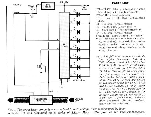
Copyright by Bill Bytheway, K7TTY February 2012