|
Automotive Audio Alarm
Easy-to-build circuit sounds an alarm so you won 't miss your car’s visual warning.
People often fail to notice immediately when a red indicator on the dashboard of a car lights to warn that service is required. The “Audible Car Protection Alarm” described here corrects this problem by simultaneously is suing an audio signal when a dashboard warning indicator is activated. It can spell the difference between a minor and a major car repair, or even save lives.
When any one or more of the warning indicators in your vehicle lights, the audio alarm sounds an insistent beeper. Then you can check the indicators to determine what service is required.
In addition to serving as an automatic fault monitor, the alarm can also remind you to turn oft headlights and rear-window defogger. The system can easily be expanded to monitor dozens of points in a vehicle’s or boat’s electrical system.
About the Circuit.
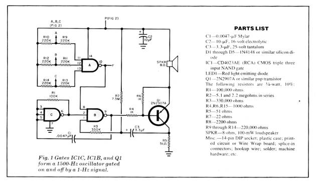
As shown in Fig.1, triple three-input NAND gate IC1 serves three separate functions. Section A operates as a conventional three-input NAND gate. If one or more of its normally high A, B, and C inputs goes low, the pin - 10 output of this gate also goes high.
Section B, also used as a three-input NAND gate, has a 1500-Hz signal applied to its pin-2 input, a 1-Hz signal applied to its pin-1 input, and the output from section A of IC1 applied to its pin-8 input. Hence, when the output from section A goes high, the circuit oscillates at 1500 Hz and is gated on and off at approximately half-second intervals.
Section C of IC1 is configured as an inverting amplifier whose output is coupled back to its input via R1 and oscillates at a frequency determined by the values of R1 and C1.
The output of section B drives Q1, whose collector load is a conventional miniature 8-ohm loudspeaker. The combination of C3, R2, and R3 functions as the system’s 1 - Hz oscillator. Capacitor C3 charges through R2 and discharges through R3. This capacitor must be initially charged before the circuit can oscillate. With the value shown for C3, a delay of about 15 seconds is provided before the alarm enables. This allows time for normal engine starting and the build-up of oil pressure. Consequently, during normal operation, the alarm will not sound.
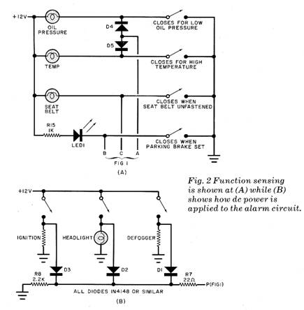
To see how the circuit operates under actual in-use conditions, let us assume that the oil pressure drops. As shown in Fig. 2A, the oil-pressure sender grounds the oil-pressure lamp, which then comes on. Simultaneously, the cathode of D4 is placed at ground potential. At this point, D4 conducts through R10 and pin 11 of IC1a goes low, causing the output of this gate to go high. As long as C3 is charged, IC1a allows the 1500-Hz oscillator to operate. When the potential across C3 reduces sufficiently, the oscillator ceases operating until C3 re charges. Therefore, the 1500-Hz oscillator is gated on and off by the R2, R3, C3 circuit at 0.5-second intervals. The beeping of the alarm continues until all of the circuit’s A, B, or C inputs are ungrounded.
In Fig. 2B, diodes D1 through 03 are connected to the ignition, headlights, and defogger (if any) circuits so that when any of these switches is closed, the associated diode is forward biased and conducts to apply power to the alert circuit via R7 and its associated C2 filter capacitor.
As an example of the foregoing, assume that the ignition is turned off, but either the headlights or the defogger is left on. The alarm will then receive power through the diode attached to the headlight or defogger switch, thereby sounding off and continuing to do so until the headlight or defogger switch is turned off. This is because when the engine is turned off, the oil pressure drops to close its sensor switch, thus activating the alarm. This action will also occur even if the oil-pressure lamp is burnt out, since the A input will still be grounded. The rear window defogger is also included since in many cars, this accessory will still operate when the ignition is turned off.
Construction. The simple circuit that makes up the system can be wired by any convenient means, including a print ed circuit board, Wire Wrap, and point to point. Since there are no high frequencies with which to contend, lead dress is not critical.
The alarm can be mounted in any box that will accommodate it and the speaker. A barrier strip, mounted on the enclosure, can then be used to make all power, ground, and sensor connections.
The diode coupling technique shown in Fig. 2A can be used to increase the number of sensing points to monitor other elements in a mobile system. Each NAND-gate input can handle a large number of inputs, connected in parallel.
Note in Fig. 2A how a LED parking brake set circuit can be added to the alarm circuit. The switch associated with this sensor can be a conventional microswitch mounted so that, when the parking brake is set, the switch closes. The LED can be mounted on the dash board and suitably identified.
Installing the System. Before the alarm is installed in a vehicle, it should be tested for proper operation. Connect a 9-volt battery between the ignition in put and ground. Temporarily connect sensor input A to ground. After about 15 seconds, the alarm should begin to beep. Disconnect the sensor input from ground; the alarm should cease beeping. Repeat this procedure with sensor inputs B and C. The positive terminal of the battery can be connected with a jumper wire to the headlight and defogger inputs to test the operation of these functions.
Make all connections to the various points in the vehicle’s electrical system securely and with care, preferably with splice-in connectors where possible. If you use a strip-and-wrap splice, make sure you cover each connection with vinyl electrical tape.
Dress all wires to protect them from mechanical and heat damage. Do not connect the ignition input to the ignition coil; otherwise, it may be damaged by transients from the coil. It goes to some accessory that is powered only when the ignition switch is turned on. Make sure that the headlight and defogger input power connections are made as shown in Fig. 2B.
After installation is complete, turn on the ignition but do not start the engine. (Set the ignition switch to the ON position only.) Since the low-oil pressure switch will be closed, after the delay period, the alarm should begin to beep. Turn on the headlights and turn off the ignition. The alarm should continue to beep and stop only when you switch off the headlights.
The alarm circuit can be used for monitoring other dc electrical systems. If failure modes are indicated by a “high” voltage, these can be diode OR’ed at input F (see Fig. 1) with the output of IC1a.
|
Copyright by Bill Bytheway, K7TTY February 2012