|
AUDIO VOLUME BOOSTER OVERCOMES OUTSIDE NOISE
Increases audio level when external noise is too high
IF YOU live near a busy airport, highway, or railroad, you are very familiar with the problem of interrupted radio, TV, and audio sys tem listening because external noise frequently overcomes the level of the program you want to hear.
The automatic audio augmenter described in this article constantly monitors external noise, and if that noise rises above a preset level, the augmenter raises the volume of the audio system to which it is connect ed. When the interfering noise sub sides below a preset threshold, the augmenter returns the audio volume to normal.
Circuit Operation.
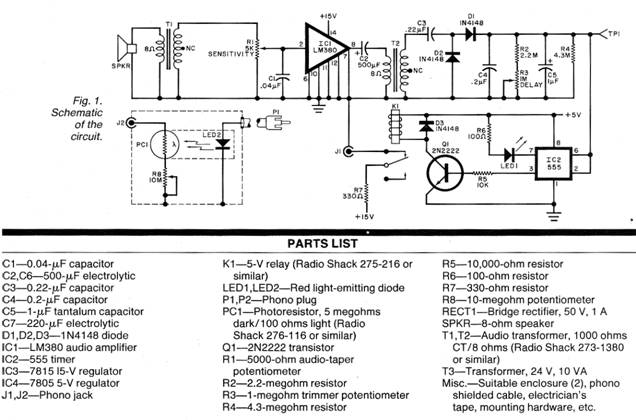
As shown in Fig. 1, the external noise is picked up by a speaker mounted at a window or other location external to the listening area. The speaker is transformer-coupled to SENSITIVITY control R1 for application to audio amplifier IC1. The amplified noise signal is coupled via C2 and step-up transformer T2 to a voltage doubler consisting of C3, C4, D1, and D2 that converts the audio signal into a dc voltage. This voltage is stored in C5, which is constantly being discharged by R2, R4, and R3. DELAY control R3 allows the discharge time to be adjusted. (The stored dc voltage can be measured at test point TP1.)
The dc voltage across C5 is applied to the threshold and trigger (pins 6 and 2 respectively) of timer IC2. As a monostable, IC2 is triggered by bringing the trigger input below a lower threshold (about 2 V). This makes pin 3 go high. When the trigger level rises above the upper TTL threshold, pin 3 goes low and remains low until the trigger level again drops below the 2-V threshold.
When pin 3 on IC2 is high, transistor Q1 conducts and closes the contacts of relay K1. This action applies a dc voltage, via R 7, to the center connector of phone jack J1, whose outer shell is ground. When pin 3 goes low, Q1 cuts off, K1 is released, and the voltage is removed from J1.
A second part of the device — consisting of LED2, photo-sensitive resistor PC1, and level-set potentiometer R8—is cable-connected via F1 to J1. This part of the audio augmenter circuit is arranged so that when the LED is powered, its emitted light falls on the sensitive surface of PC1. When PC1 is illuminated, its resistance decreases, and when it is in the dark, its resistance increases. This resistor, in series with R8, is connected across J2.
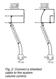
As shown in Fig. 2, a shielded cable is connected to J2, via P2, to the system volume control. The illustration shows how connections should be made to two of the most common types of volume-control circuits. Experiment with shield ed/center-conductor wiring polarity to minimize hum pickup.
Thus, when no external noise is detected, LED2 glows and a low-resistance shunt consisting of PC1 and R8 is connected across the system volume control. This causes the system volume level to assume a relatively low level that is set by the system control and the adjustment of R8.
But when an external noise is detected, K1 opens to remove power from LED2. When this LED extinguishes, PC1 reverts to its very high resistance state, thus removing the effect of the PC1-R8 shunt from the system volume control. As a result, the system volume increases.
When the external noise ceases, the audio volume remains high until the dc voltage across C5 is discharged. (This time period is determined by the setting of R3.) Once C5 has discharged, IC2's pin 3 goes high, causing LED2 to glow and place the PC1-R8 shunt back across the system volume control, reducing the audio to normal, preset levels. Note that when high volume (augmenting) is required, LED1 glows.
The power supply required is conventional, and uses a bridge rectifier and 15- and 5-V regulators (Fig. 3).
Construction.
Since layout is not critical, either perf-board or wirewrap can be used, or a small pc board can be designed and fabricated. All components except the speaker, LED2, PC1, and R8 can be installed on the selected circuit board.
LED2 and PC1 are physically mounted so that the glowing face of the LED is adjacent to the sensitive surface of PC1. The two are then taped with dark electrician’s tape to form an optoisolator in a light-tight package.
This optoisolator, together with R8 and J2, is mounted within a small enclosure that can be cable connected via P1 to J1 on the main electronics package. Everything else is mounted in an enclosure with the power supply. LED1 should be mounted so that it is visible through the cover, and a dial plate should be used for SENSITIVITY control R1. The power cord can exit via a grommetted hole on the rear apron.
To test the system, connect an ohmmeter between the center and ring of J2. With the power off, there should be a very high resistance (many megohms) at this point. A few moments after the operating power has been turned on, this resistance should drop to a much lower value—which can be adjusted via R8. You may hear relay K1 click as power is applied.
Use a schematic of your radio, TV, or audio system to determine where to attach the leads coming from J2, in accordance with Fig. 2. If you have a transformer-less “ac/dc” system, keep in mind that the system chassis may be “hot” with respect to the power line and ground. This can be a problem, since it could make the augment chassis potentially dangerous.
Measure for an ac voltage between the volume control and earth ground—it should be zero. If there is an ac voltage present, reverse the line cord plug at the wall socket and re-check for the ac voltage. It should be zero. If it is not, you can not use the augmenter safely unless the audio system’s power supply is modified to run off a transformer.
If reversing the wall plug results in a zero ac voltage between the system volume control and ground, make sure that this plug orientation cannot be tampered with, in the interests of user safety. This is very important.
Adjustment.
The augmenter’s speaker (SPKR) should be mounted at a window, or outside if possible, so that it will pick up external noise easily. Conventional speaker leads can be used to make the connection to T1. Locate the optoisolator close to the audio system being controlled, and connect it to the main augmenter circuits via a cable to F1.
With the augmenter connected and no noise present, turn on the audio system and set its volume to normal listening level. (This volume will now be determined by both the regular volume control and the setting of R8) Now, when the augmenter detects noise, the system volume should automatically rise. Trial-and-error will determine the best location for the augmenter’s speaker, the settings of the SENSITIVITY control and R8 for increased volume, and the adjustment of R3 for providing time delay.
|
 Now
create a loud noise or tap the speaker and note that the resistance
across J2 goes up, and re mains up for a brief interval after the
noise ceases. The delay observed is determined by the setting of R3.
Now
create a loud noise or tap the speaker and note that the resistance
across J2 goes up, and re mains up for a brief interval after the
noise ceases. The delay observed is determined by the setting of R3.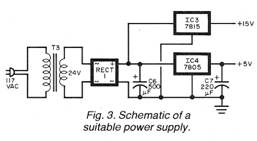
Copyright by Bill Bytheway, K7TTY February 2012