|
Adding an Output Interface to a Digital Timer
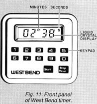
One of the handiest gadgets in my office is a West Bend Electronic Timer This compact, crystal-controlled device is a digital countdown timer that sounds an alarm at the conclusion of a preset, user-programmable interval. The interval can range from 1 second to 99 minutes and 99 seconds.
Figure 11 is a pictorial view of the timer’s front panel. The unit is operated by keying in the desired interval and pressing START. When the count reaches OOM OOS, the timer emits a rap id series of attention-getting chirps. The chirps will sound for one minute or until the STOP/RESET key is pressed.
The countdown can be halted temporarily by pressing STOP/RESET. The countdown will resume when START is pressed. Pressing STOP/RESET twice clears the display to OOM OOS.
Adding Output Leads. On the back of the timer is a handy clip that allows the unit to be attached to a belt or pocket. It also functions as a desk stand. A magnet in the clip permits the timer to be temporarily attached to a metal surface.
Just below the bottom of the clip is a small Phillips screw. When this screw is removed, the back panel of the timer can be gently pried away from the front panel by inserting a flat screwdriver blade in the continuous, thin slot that separates the two panels. Be sure to pry along the bottom slot near the screw hole to avoid breaking the plastic snap retainers on the inside, upper edge of both panels.
After you lift the back panel away, temporarily set aside the power cell. Note the wires leading to a cylindrical component in the back panel. This is the piezoelectnc alerter. The volume of sound that can be delivered by an alerter so small is truly remarkable.
Use a grounded or battery powered soldering iron to remove both alerter leads from the circuit board. Wrap appropriately colored lengths of wrapping wire around the exposed wires of each lead, solder in place, and then solder the two pairs of connection wires back to their original locations on the circuit board. Be sure to solder the leads to the correct locations, for if their polarity is reversed the alerter will not sound.
Replace the battery (plus polarity side up) and check the timer for proper operation. Now you are ready to assemble the interface circuit.
An SCR Interface. The timer alarm signal consists of approximately eight bursts per second of 125-microsecond pulses having a 2.4-volt peak-to-peak amplitude. The pulses have a frequency of 4 kilohertz. Figure 12 shows a simple SCR interface that switches on upon ar rival of the first pulse and remains on until manually reset.
The SCR alone can control loads up to its rated capacity. I used a relay to provide isolation between the timer and the load and to increase the circuit’s switching power. Dl reduces the possibility of 8-Hz chatter while the timer’s alarm is sounding. D2 protects the SCR from reverse voltage developed across the relay’s coil when the reset switch is opened.
Not all SCR’s will be reliably triggered by the timer’s alarm signal. I had good results with Motorola’s SCR1 128 and Radio Shack’s 276-1067.
Incidentally, you’re on your own when you modify a manufactured electronic device such as this timer! Any warranty may be voided. And you must exercise caution to avoid damaging the timer’s internal circuitry. You must also use caution and follow appropriate safety requirements should you use the modified timer to control line-powered devices.
Interface Applications. You can use the modified timer to control a dark room enlarger, outdoor lighting, battery chargers, appliances, radios, and television sets. For best results, install the interface and relay on a small board and mount it adjacent to a 9-volt battery holder in a suitable enclosure. Provide suitable plugs and jacks for connecting the timer to the interface and the interface to the device being controlled.
The timer can be clipped to a suitable shoulder or extension on the interface enclosure. Alternatively, you can use adhesive-backed squares of hook and loop fasteners. This will allow you to remove the timer when it’s not being used to control the interface.
Going Further. The timer I used is made by The West Bend Company (Box 1976, West Bend, WI 53095). I purchased mine at a department store for about $12.
Recently I’ve seen advertisements from three other companies showing timers having an almost identical appearance to the West Bend unit, but selling for as much as $29.95! You may be able to modify these and other digital timers with the help of the circuit in Fig. 12. In any case, shop around for the best buy. You may save more than enough to pay for the interface circuit.. . and possibly enough to buy a second timer!
|
 Drill a small hole in the timer’s
back panel. Then thread the two wrapping wire leads through the hole
and replace the back panel. Be sure the battery contacts are
properly aligned before replacing the screw. (You can see the
contacts by removing the battery cover on the back panel.)
Drill a small hole in the timer’s
back panel. Then thread the two wrapping wire leads through the hole
and replace the back panel. Be sure the battery contacts are
properly aligned before replacing the screw. (You can see the
contacts by removing the battery cover on the back panel.)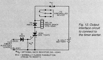 WARNING: You must follow safe
wiring procedures if you use this circuit to control devices powered
by the household line. Insulate all exposed connections. Do not
exceed the contact ratings of the relay. The timer and interface
should not be used for any application in which a circuit
malfunction might cause injury to people or property.
WARNING: You must follow safe
wiring procedures if you use this circuit to control devices powered
by the household line. Insulate all exposed connections. Do not
exceed the contact ratings of the relay. The timer and interface
should not be used for any application in which a circuit
malfunction might cause injury to people or property.Copyright by Bill Bytheway, K7TTY February 2012