|
A simple CMOS oscillator
OSCILLATORS ARE PROBABLY THE MOST popular kind of circuit around. Just about every piece of equipment you can buy has at least one oscillator buried inside it. More than likely there are several, be cause different kinds of jobs call for different kinds of oscillators.
We’ve discussed several types of oscillators in this column, but we’ve never even mentioned the one that’s probably the most useful of all: the crystal oscillator. Once upon a time it was anything but simple to design one of those sings, but, like many other things, that design difficulty is now a matter of history. These days, a reliable crystal oscillator can be built easily by throwing together a handful of easy-to-find parts.
A simple crystal oscillator
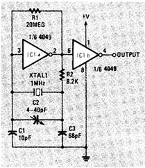
The circuit shown in Fig. 1 is a good example of just how simple it can be to build a crystal-controlled oscillator. To understand how the circuit works, temporarily ignore the crystal and the capacitors. What’s left is an inverter set up as a linear amplifier, another circuit we’ve discussed in this column be fore. (See, for example, the negative-voltage generator in this column in the March 1986 issue.)
By adding the crystal and the capacitors to the feedback path, we turn the amplifier into an oscillator and force it to oscillate at, or at least very near, the crystal’s resonant frequency. The trimmer capacitor (C2) allows you to adjust the actual operating frequency of the circuit. The crystal should be a parallel-resonant type; maximum frequency will depend partly on supply voltage, but you should have no trouble getting at least 1 MHz. Use quality mica capacitors to minimize thermal drift.
The circuit is built from a simple inverter, but you can use just about any CMOS gate that can be set up as an inverter. A TTL gate doesn’t behave well when you force it into linear operation. The bandwidth is limited, it sucks up a lot of current, and all sorts of other nasty things can happen.
If you use a two-input NAND or NOR gate instead of an inverter, you can use the other input as a gate to turn the buffer. And, no matter what sort of gate you use, it’s a good idea to buffer the output with another gate. Often you can simply use another gate in the same package as the buffer. And if you have more than one gate available, you can feed the buffered output through another inverter. That will give you two outputs that are equal in frequency but 180 degrees out of phase. Microprocessor and other circuits occasionally need out-of-phase clock signals.
If you need other output frequencies that are integrally related to the crystal’s frequency (100 kHz, 50 kHz, 10 kHz, etc.), they can be obtained using dividers.
Setting up a home lab
I receive many letters from people asking what basic equipment one needs for doing electronic circuit design at home. That’s an easy question to ask, but a difficult one to answer. What you need depends entirely on what you want to do. At the risk of having everyone disagree with me, I’ll say that I think a minimum workbench would include a multimeter, a logic probe, a pulse catcher, an RC substitution box, a variable power supply, breadboards, and a good soldering iron. After you acquire those basic items, you can start thinking about oscilloscopes and other more expensive items. But, as you get more and more involved in circuit design you’ll also find that the handiest stuff to have around isn’t necessarily what you ordinarily think of as test equipment. No workbench can be considered complete without a slew of debounced switches, digital display circuits, oscillators, variable frequency generators, and other circuits that you can de sign and build yourself.
If you find yourself using the same sort of circuit over and over on the bench, it’s a good idea to take the time to refine it and put it on a PC board. It will make circuit development easier, and you’ll find that you can drop the PC layout right into some other circuit.
|
Copyright by Bill Bytheway, K7TTY February 2012