|
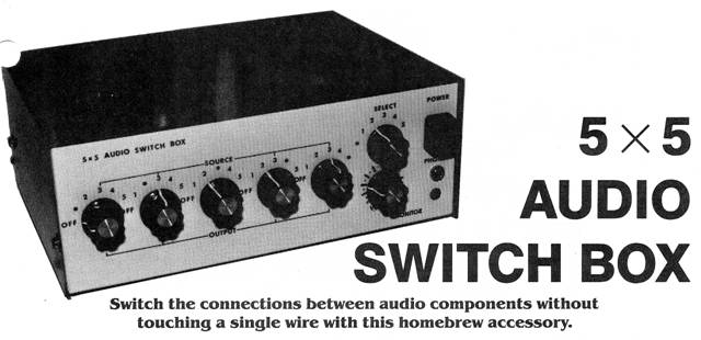
5x5 AUDIO SWITCH BOX
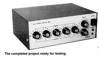
Switch the connections between audio components without touching a single wire with this homebrew accessory.
IF YOU’VE EVER HAD TO SORT THROUGH A RAT’S NEST OF cables to get the right plug and jack combination to make a recording, or to play a device through your stereo amplifier, you’ll appreciate the 5 x 5 Audio Switch Box. The Switch Box provides a convenient means by which to switch between 5 inputs and outputs in any combination, and features a built-in stereo headphone amplifier that allows you to monitor any of the outputs.
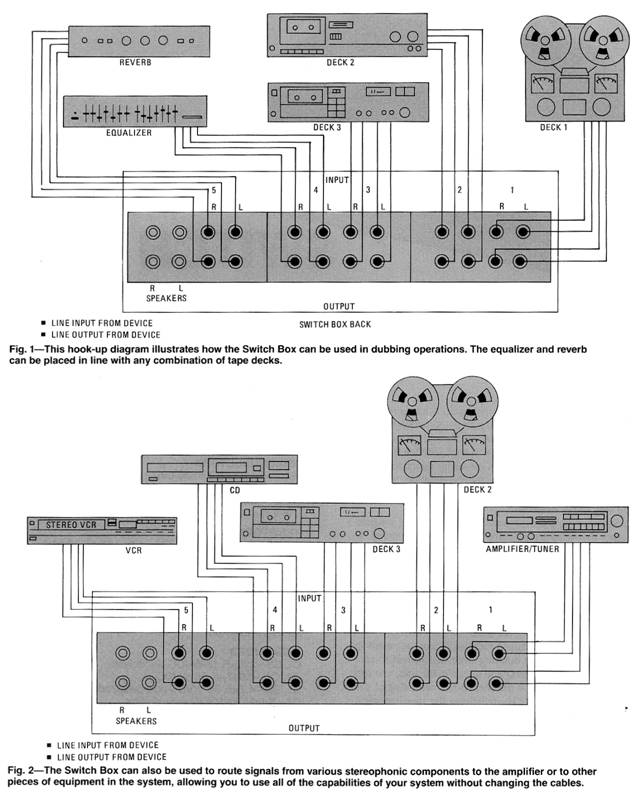
The Switch Box was designed to help in making musical demo tapes through a setup similar to the one shown in Fig. 1. However, it might just as easily be used in the home-stereo system setup (like that shown in Fig. 2), or in practically any system where needed.
Although the Switch Box’s monitor amplifier was designed to be used with a mini stereo headset, it is capable of driving a standard headset or 8-ohm speakers. (But don’t expect hi-fidelity audio; it’s adequate for monitoring.)
The advantage of the built-in monitor is most apparent in the Fig. 1 setup. If you’re dubbing from reel-to-reel to cassette, and there is an equalizer and reverb in the line, you can compare the raw output of the reel-to-reel with that of the equalizer or reverb simply by switching the monitor-select switch.
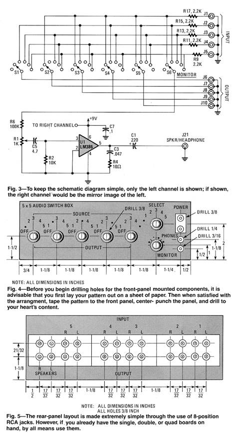
The schematic diagram in Fig. 3 shows one channel of the Switch Box; for stereo operation, two such circuits (tied to the same set of dual-gang 6-position switches). To make construction as easy as possible, the Switch Box is designed around commonly available components; all of them may be purchased at a Radio Shack or just about any well-stocked parts supplier. Although wiring the jacks and switches is time consuming, it is not difficult, making the project one that anyone can tackle regardless of his or her level of skill.
Construction
Begin construction by preparing the case. A metal case is important for shielding, so if you substitute another case, make sure that it’s large enough to accommodate the switches and jacks and that the entire enclosure is metal.
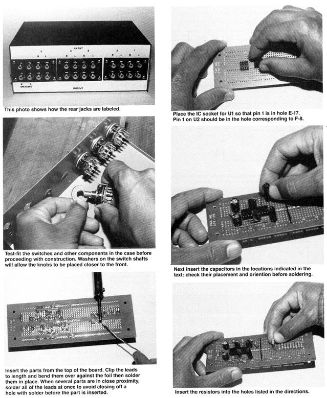
Figure 4 shows the front-panel layout used in the author’s prototype of the Switch Box. (All dimensions are given in inches.) You can either lay out your circuit panel in a similar arrangement or try something more to your liking. Figure 5 shows how the input/output rear-panel jacks were laid out in the prototype. Note that all inputs are positioned at the top, while all outputs are at the bottom. (Again, all dimensions are given in inches.) Drill holes (both fore and aft) for the panel-mounted components.
The case is then covered with a protective plastic film; with the film in place, the hole positions are center-punched to keep the bit reasonably stable during drilling. It’s a good idea to use some sort of solid backing for the panel while drilling. One way to provide a solid backing is to clamp a piece of 2 x 4 to your workbench, with one end extending about 3 inches over the edge of the bench. After drilling, remove rough edges and the protective film from the case. And then rub-on lettering may be used to label the switch and jack locations.
may be used to label the switch and jack locations.
The Panel-Mounted Components
Once the front- and rear-panel drilling is complete, mount three eight-position (six four-position or 12 two position) phono-jack boards to the rear panel, using sheet-metal screws. It's OK for the ground terminal of the jacks to touch the metal case, but if the center terminal touches, remove the board and enlarge the hole with a file.
With the rear panel out of the way, turn your attention to the front-panel switches. The switch knobs should be mounted as close to the front panel as possible, meaning that the excess shaft length of each switch must be cut off. The least nerve-wracking way to accomplish that is to clamp the waste end of the shaft to your bench and, with a hacksaw, cut off the excess.
After the excess has been cut away, place a 5/16 inch washer over the threaded shaft, loosely mount the switches, and make sure that the knobs are close to the front panel.
With the case complete, you are ready to begin putting together the electronics.
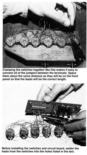
Begin with the switches. Each switch has 12 terminals around the outside and two in the center. Turn the switch counterclockwise until it stops to determine the first terminal of each, which will serve as the off position; therefore no connection is made to those terminals. Bend them slightly to mark their locations. Next turn the switch shaft one click in the clockwise direction, which will be input 1; one more click and you’re at the input-2 position, and so on. Remember that the selectors are double-pole, six-position switches; one terminal (pole) is for the left channel and the other for the right.
For convenience, the author arranged the switches so that all of the left terminals were on top and the right terminals on the bottom. To make it (next to) impossible to connect the input and the output of the same device together, no connection is made to position 1 of S1; position 2 of S2, and so forth.
Next run jumpers from switch to switch to
connect all of the left-channel position 1 terminals, and another to
connect all of the right-channel position 1
Switch S3 lines up with the input terminals on the circuit board. Solder two-inch lengths of wire to all eight active terminals of S3. Also solder wires to the position 3 terminals of switch S4 since the number-three input is not connected to S3. They’ll be connected to the circuit later.
Next cut five pieces of shielded, two-conductor cable. The cables should be long enough to reach from the switches on the front panel to the jacks on the back panel. Attach the two center conductors to the two center terminals on the switches; one terminal for the left channel and the other for the right.
Solder short pieces of insulated wire to the shield of each cable and insulate the connection with tape or heat-shrink should be about two inches long.
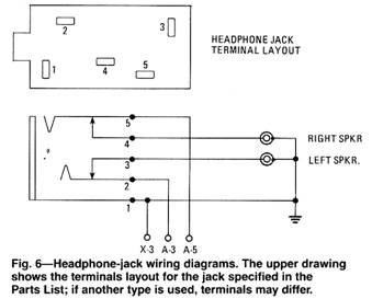
The ground lead connects to hole X-3, the left channel to A-3 and the right to A-S. Solder short, insulated wires to LED1 and insulate the connections with tubing. Attach the anode lead to the circuit board at A-l and the cathode at X-1. Attach 3-inch leads for the power switch to the circuit board at H-2 and I-1.
The components can now be mounted in the case. Attach the PC standoffs to the case but leave the PC board unattached for now. Place the volume control and the switches in their holes and secure the nuts. Push the LED into its hole in the front panel; it should fit tightly to stay in place. If the LED is loose in its hole, use a little glue to secure it. Put the headphone jack in place on the front panel and secure it.
The power switch pushes in from the front of the panel and is secured with a nut on the back. After it is in place, connect it to the circuit board. Solder a three-inch long lead to the “Y” ground bus on the circuit board. Scratch the paint from a small area on the bottom of the case and solder the ground lead to the case at that point. That ensures a good ground connection to the case providing shielding from outside noise. Attach the battery holder to the case with a small machine screw and a nut. Place the nut on the bottom and cut the screw off flush with the nut.
Now connect the shielded cables from the circuit board and the switches to the jacks on the rear panel. The cable from switch number 1 connects to output jack 1 (left and right), switch number two to number two output and so forth.
The cables from the circuit board attach to the input jacks in as follows: left input jack Jl to position J-47 and right input jack to J-46; L2 to J-44 and R2 to J-43; L3 to J-41 and R3 to
able tubing. Connect all of the shield wires together and then solder a short lead from them to the X ground bus on the circuit board.
Now connect the leads already soldered to switches S3 and S4 to the circuit board: left-channel, position 1 (L1) connects to the circuit board at position A-47 and right-channel position 1 (R1) to A-46; L2 to A-44 and R2 to A-43; L3 to A-4l and R3 to A-40; L4 to A-38 and R4 to A-37; L5 to A-35 and R5 to A-34. Solder two leads to the center terminals of the monitor-select switch and connect the left-channel lead to hole A-23 on the circuit board and the right to A-22.
Attach two-inch lengths of wire from volume control R1 to the circuit board. With the control placed so that the terminals are on the left side as viewed from the front, the top two terminals are the ground terminals; connect them together and use one lead to attach to hole X-l7 on the circuit board. Connect the center terminal for the left channel to hole A-19 and the right channel to A-l8.
The bottom terminal for the left channel attaches to hole A-21 and the right channel to A-20. Wire the headphone jack as shown in Fig. 6. Use a piece of shielded cable long enough to reach from the front panel to the rear-panel jacks for the speaker output. The leads that attach to the circuit board J-40; L4 to J-38 and R4 to J-37; L5 to J-35 and R5 to J-34.
When attaching the cables to the jacks, twist the shield wires into two leads and attach them to the two ground terminals.
Connect the cable from the headphone jack to the two speaker terminals on the rear panel. The two jacks above the speaker jacks are unused.
Snap in a 9 volt battery and the unit is ready to test.
Circuit Board Assembly
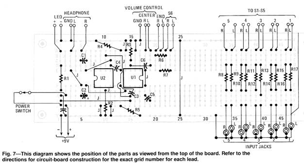
The author’s prototype was built on a pre-etched board (available from Radio Shack) on which each hole is identified by a row letter and a position number. Fig. 6 shows the parts layout of the circuit board as viewed from the top. The following instructions give the location of each part on the circuit board. When you insert the component, clip and bend the lead over to mechanically hold the part in place; then solder with a low-wattage iron. Where several parts are close together, you may want to wait until all of the leads are in place before soldering, so you won’t have any trouble inserting adjacent components.
1. Mount the IC sockets on the board (see Fig. 7). The first socket is mounted so that pin 1 is in hole F-8. The second socket is turned around so that pin 1 is on the other half of the board in hole E-l7.
2. Jumpers are used on the top surface of the board to connect some of the traces. Bare wire can be used for the short jumpers but insulated wire should be for longer runs or whenever one jumper crosses another. Keep the jumpers short and run them as directly as possible. Install jumpers between the following pairs of holes: J-25 to Y-25; J-9 to Y-9; I-11 to Y-11; A-14 to X-14; 1-1 to 1-15; H-15 to B-10; C-11 to E-6, 0-14 to F-6; F-S to E-3; F-18 to E-l8; H-10 to J-19.
3. Mount the capacitors, referring to the Parts List for their values. Be sure to observe polarity where indicated. Install the capacitors in the following pairs of holes: C1 between C-6 and C-S; CS between 1-19 and H-18; C2 between + H-6 and H-5; C6 between D-15 and D-19; C3 between H-14 and F-13; C7 between H-1 and Y-2: C4 between D-11 and E-13.
4. Mount the resistors in the following pairs of holes: R1 between D-1 and 0-1; R10 between D-37 and G-37; R2 between 0-10 and Y-10; R11 between D-38 and G-38; R3 between C-15 and X-15; R12 between D-40 and 0-40; R4 between A-13 and X-8; R13 between D-41 and 0-41; RS between J-l3 and Y-l7; R14 between D-43 and 0-43; R6 between B-20 and B-22; R15 between D-44 and 0-44; R7 between E-2l and E-23; Rl6 between D-46 and G-46; R8 between D-34 and 0-34: R17 between D-47 and G-47; R9 between D-35 and G-35.
5. Connect the battery clip with the positive lead to J-2 and the negative lead to Y-1.
6. Cut five 4-inch lengths of two conductor shielded cable and attach them to the circuit board as follows: L1 to J-47, R1 to J-46, and GND shield XX to Y-47; L2 to J-44, R2 to J-43, and GND shield XX to Y-44; L3 to J-41, R3 to J-40, and GND shield XX to Y-41; L4 to J-38, R4 to J-37, and GND shield XX to Y-38; LS to J-35, RS to J-34, and GND shield XX to Y-35.
7. When all soldering is complete, install the IC’s in their sockets. Be sure to line up pin 1 correctly; the two IC’s are oriented with pin 1 on opposite sides of the board.
Various audio components are connected to the Audio Switch Box through shielded cables. The output of the device connects to the input of the Switch Box, whose output (in turn) connects to the input of another audio device. Switching can be accomplished with or without power turned on, because power is needed to operate the monitor only. Battery power is used to avoid any possibility of introducing hum into the circuit. For limited use, the battery lasts a long time. But if desired, a power supply could replace the battery. Just be sure that the power supply is well shielded and filtered.
As an initial check, turn all of the output switches to OFF and the monitor power ON. Turn on all of the devices connected to the box and set them for some type of output (play a tape, turn on the FM tuner, etc.). Now turn the monitor-select switch to each of the different settings. You should hear the output of the selected device in the headphones. Next try recording from one device to a tape deck. |
 Operation
Copyright by Bill Bytheway, K7TTY February 2012