|
4 TO 3 WIRE
TAILLIGHT CONVERSION
Connect brake and turn signal lights of
trailers to foreign cars
BY MICHAEL S. CRANMER
 VIRTUALLY all foreign cars and trucks have
taillights that use separate bulbs for the turn signals and brakes.
This type of system uses a 4-wire configuration, which makes it
possible to have the turn-signal light blinking and the brake light
on at the same time on the same side. A problem occurs, however, if
you want to hook up a U.S. - made trailer to the foreign car or
truck. Trailer lights are usually wired on a standard 3-wire system.
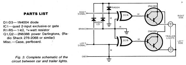
That is, the turn signal and Circuit Operation. The circuit is
powered by the signal display system on the foreign car or truck.
The three diodes, in parallel with the inputs, conduct current to
the power Darlingtons and the EX-OR power supply pin. The diodes
also prevent current from conducting back to another gate input.
(These diodes are not needed if a separate 12-volt line is run from
the battery.) The three l-kilohm resistors, tied to the inputs of
the gates, are used to pull to ground the input gate volt age. (This
is needed to keep the gate inputs from floating high.) The other
brake light share the same bulb. With this configuration, if the
brake is on and the right signal is on, the right bulb blinks while
the left bulb indicates brake operation. VIRTUALLY all foreign cars and trucks have
taillights that use separate bulbs for the turn signals and brakes.
This type of system uses a 4-wire configuration, which makes it
possible to have the turn-signal light blinking and the brake light
on at the same time on the same side. A problem occurs, however, if
you want to hook up a U.S. - made trailer to the foreign car or
truck. Trailer lights are usually wired on a standard 3-wire system.
That is, the turn signal and Circuit Operation. The circuit is
powered by the signal display system on the foreign car or truck.
The three diodes, in parallel with the inputs, conduct current to
the power Darlingtons and the EX-OR power supply pin. The diodes
also prevent current from conducting back to another gate input.
(These diodes are not needed if a separate 12-volt line is run from
the battery.) The three l-kilohm resistors, tied to the inputs of
the gates, are used to pull to ground the input gate volt age. (This
is needed to keep the gate inputs from floating high.) The other
brake light share the same bulb. With this configuration, if the
brake is on and the right signal is on, the right bulb blinks while
the left bulb indicates brake operation.
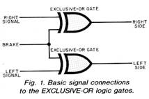
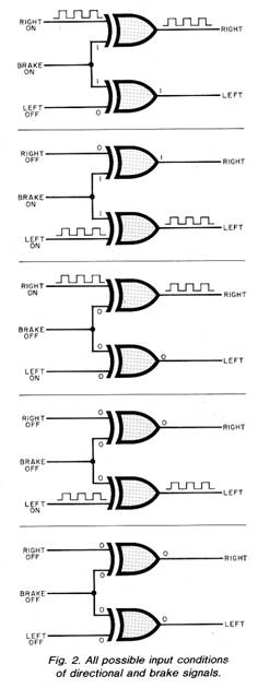
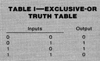 The problem of connecting a 4-wire signal
system to a 3-wire system can be solved by using an EXCLUSIVEOR gate
between the two systems. The truth table for this logic gate is
given in Table 1 while the basic connections to the gate are shown
in Fig. 1. Figure 2 shows all possible input conditions of left or
right signal and brake light with the resultant output of the
EXCLUSIVE-OR gate. Note that the ground wire is not shown in Fig. 2.
The complete schematic of the circuit is shown in Fig. 3. The problem of connecting a 4-wire signal
system to a 3-wire system can be solved by using an EXCLUSIVEOR gate
between the two systems. The truth table for this logic gate is
given in Table 1 while the basic connections to the gate are shown
in Fig. 1. Figure 2 shows all possible input conditions of left or
right signal and brake light with the resultant output of the
EXCLUSIVE-OR gate. Note that the ground wire is not shown in Fig. 2.
The complete schematic of the circuit is shown in Fig. 3.
1-kilohm resistors are used as current
limiters. Unused input pins on each gate must be tied to or ground.
Also it would be advisable to place an in-line fuse on the 12-volt
supply.
 Construction. Construction.
Building this circuit is simple and
inexpensive. Most of the parts can be mounted on a piece of perf
board with the power Darlingtons mounted on heat sinks. Usual care
should be taken with the CMOS IC to insure that it is not damaged by
static electricity.
|