1. WHY CRYSTAL CONTROLLED RTTY? For stability. Also to find the same frequency any time you want without having to "guess at it". Another advantage not immediately apparent is the ability to use simple and inexpensive c.w. transmitters in lieu of the normal transmitter which in the case of SSB units may employ 25-30 tubes. A suitable CW. type transmitter can be used with a total of perhaps three tubes including the crystal oscillator section. Certainly one of the advantages of a good crystal oscillator is the ability to keep a given frequency from "cold" to "warm" hours later. No v.f.o. normally used by an amateur can compare in this respect.
2. HOW STABLE ARE VFO’S?
The best answer to this is: "Not Very." The figures given for most VFO’s indicate over a 24—hour period of time that the best you can expect is on the order of 1 x 10^4
which is the equivalent of about 100 Hertz per megahertz. This would be about 360 Hz. on the 80m band for example. Thus you can see the reason some companies have for placing the frequency of their VFO’s to 2.5 MHz. (Collins) The use of"PTO’s" rather than "VFO’s" can greatly improve the picture, as it is the variable capacitor that introduces nearly all the drift in a VFO. In a PTO such as is used by Collins, there is no variable capacitor and thus the drift can be held to a small amount when compared with other units. There will still be substantial "warm-up" drift, however, and due to heat generated after long periods of transmission such as RTTY, some drift will still be evident. The PTO used in the receiver gives an overall stability the transmitter cannot match, as the heat level in the receiver stays at a uniform level, and many operators (if interested in stability) never turn their receivers off.
3. HOW STABLE DO WE NEED?
This question YOU have to answer. It depends on what you want to do. Since it is the other fellow who has to keep his hand on his receiver, you may be satisfied with that clunker of a VFO you have always been using. If you are interested in good, stable operation, then 100 to 200 cycles during an entire QSO might be your goal. If you are interested in unattended autostart, then you would want long term stability of 15 to 20 Hz. or less.
This depends primarily on the shift being used. Most unattended RTTY auto-start nets have found narrow shift (170 Hz) to be much more reliable than 850 Hz. shift. Since the other fellow’s receiver will have some drift, the amount by which your transmitter may be off will add to the amount by which his receiver might be off. A guess based on several years of practical experience would be perhaps +/- 50 Hz. for 170 shift autostart. It would be nice to keep the transmitter frequency within say 50% or less of this tolerance to allow for some receiver drift at the other end. A good receiver can stay within 25-35 Hz. per day, although this narrows your selection of "brand names" down to only a few.4. WHAT ARE THE REQUIREMENTS FOR AUTOSTART?
5. HOW CLOSE WILL A GOOD CRYSTAL OSCILLATOR STAY?
Until recently, a normal crystal oscillator with decent components would only stay to perhaps 75 Hz. per day. This was (as we now know) due primarily to the crystal and not to the oscillator. Crystal ovens were used where better stabilities than this were required. New crystal cuts now available are so exceptionally stable (without ovens) that even on 20M you can expect stability from "cold" to hours (or days) later of around � 5 Hz. and better. This is well within the most stringent tolerances for autostart.
6. HOW MUCH- CAN A CRYSTAL BE SHIFTED?
This depends on the frequency and the circuit being used, as well as the type of crystal selected. I was able to pull a normal 80M crystal over 3300 Hz. using every trick I could discover. Using these same methods, I got over 17,000 Hz. shift on a 20M crystal. As soon as you add the RTTY circuit, these figures change. If you follow the "rules", you will have no trouble in pulling the crystal at least 850 Hz. on 80M, and have enough "pull" left over to hit a specific frequency as well. Only on 80M does "maximum shift" become a problem, however, so particular attention must be given if 850Hz. is needed on 80 M. On 80 M, you can shift 850 Hz. and perhaps an additional 400-500 Hz. as well.
7. WHAT ARE THE "RULES" FOR MAXIMUM SHIFT?
A few "rules" are important for maximum shift:
1. Keep the screen by-pass capacitor fairly large. (100—150 pf. seems quite good.)
2. Use a 1N270 diode in the shifter —it’s low forward voltage drop aids In maximum shift - in any event use a germanium diode here, not a silicon diode
3. Use a phenolic core RF choke in the shifter such as a National R-50. (Not a ferrite core RF choke for maximum shift.)
4. Use a 6AK5 or 6EA8 tube.
5. Keep the grid capacitance very small (a 1.5—7 pf. trimmer)
6. Keep the grid connections as short as possible.
7. Use only "plated" type crystals, not the "pressure" type usually purchased surplus.
If you are not interested in 850 shift on 80M, then . these rules become less important and can be disregarded completely for 20M.
8. MAXIMUM STABILITY WITHIN REASON
If you are not interested in net operation or autostart, but just in good stable RTTY operation on any convenient frequency allowed, then there is little justification in spending $9 for a "HA" crystal and even the military surplus crystals selling for a dollar or two will be excellent for your purpose. Almost any crystal used in this case will compare with the very best VFO’s after the VFO has been warmed up for a day or two.
However as long as you are building the crystal oscillator anyway, you will find it won’t add but pennies to the total cost to "do it right" and added stability can be achieved. Again some rules are in order.
1. DON’T use "air variable" capacitors. This after all is what causes the VFO to have excessive drift. If you don’t believe this, just TRY to find some published curves on the drift of an air variable with temperature chances.
2. DO use "no—drift" (NPO) trimmer capacitors such as the ERIE 557 or ERIE 507 types.
3. Use silver mica capacitors (or NPO temperature compensating capacitors) for the other fixed capacitor values.
4. Use a stable crystal, such as the International "HA" type.
5. Mount all the components except the tube inside the external oscillator box. (Be sure the box Is covered on all sides Including the bottom).
6. Do not modify the existing crystal oscillator in the transmitter but build an external oscillator as shown In the schematic - this then plugs Into the "VFO" input on the c.w. transmitter.
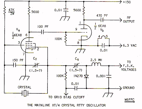
9. THE CIRCUIT
Various circuits will work, and with the ideas shown, you may want to try some other oscillator circuit. However, the circuit shown has been used successfully by many operators and can be offered as a "guaranteed" stable circuit. (Assuming you follow the "rules" for selecting components.) It can be used in conjunction with crystal ovens if you prefer them to the "HA" crystal.
10. HOW ABOUT OVENS?
Any reasonably priced oven would be a thermostat type, cycling on and off. They usually are set for 85 C, and special crystals cut to operate best at this temperature must be obtained. While these crystals are somewhat cheaper than the "HA" crystals, by the time you buy the oven and its associated transformer (they usually pull about one amp at 6 volts), you have probably exceeded the cost of the "HA" crystal, in addition to having an oscillator of bulky size with AC voltages nearby.
11. HOW DOES A COMMERCIAL OVEN AND CRYSTAL COMPARE WITH THE "HA"?
About the same. My experience with a digital counter has been that the "HA" crystal gives as least as stable results as the oven combination, without all the associated parts.
12. HOW ABOUT A "HA" CRYSTAL IN AN OVEN?
Sounds like a real winner, doesn’t it? The factory doesn’t make crystals for 85 C ovens, and they say the "HA" design should not be used at temperatures "that high". (85 C is around 185 F.) Forget about this combination.
13. SELECTING THE CRYSTAL FREQUENCY
Remember on RTTY you LOWER the frequency of the transmitted signal when you go to space. Thus you must consider the frequency of the space signal when selecting a crystal. As most amateurs refer to the MARK frequency when talking about net operation, etc., you can make an expensive mistake if you don’t read this paragraph before ordering the crystal. (In military "MARS" circuits they quote the "center" frequency between mark and space for net operation, so if you are planning "MARS" operation, be a little careful!)
The frequency printed on most crystals represents its use in a normal circuit where it is loaded to a specific capacity. Usually this is 32 pf. It canbe less — some crystals are provided for 20 pf. operation. They are normally the same crystal, only in this case it has a slightly different frequency marked on its case.
A 32 pf. crystal does not need to be used in a 32 pf. circuit, but to get the frequency printed on its case, it does. If it is put In a 10 pf. circuit, It oscillates higher in frequency, and if put in a 50 pf. circuit it oscillates lower. It is easier to raise the frequency of a crystal than to lower It before it stops oscillating.
Thus you should purchase the crystal with "space" frequency in mind, as you can then raise it easily to hit the mark frequency. Since most crystals have some error in frequency from that stamped on its case, you must also allow for this to some extent. (The "HA" crystals are ground quite accurately compared with the cheaper $3 - $4 crystals).. Since there will be some additional capacitance in the wiring to the grid leads of the oscillator, etc., we recommend that for ordering the crystal you do it this way:
850 shift
mark frequency minus 700 Hz. 170 shift
mark frequency minus 100 Hz. 850 shift (MARS)
net frequency minus 275 Hz.
As an example - let’s say you want to get on 3620.000 850 shift:
3620.000
-0.700
3619.300
So order the crystal for 3619.300. This example should suffice for hitting any frequency you are interested in.
Let’s say you want to hit 14090.000 where your transmitter doubles up from 40M:
14090. 000
-0.700
14089.300 <---- Divided by two:7044.650
And that is the way It’s done. 170 shift is identical only substitute "—100" for "—700" in the arithmetic.
You can use a 850 shift crystal for 170 shift also, for that matter, but on 80 M you can’t very well use a crystal selected for 170 shift on 850 shift and hit the same frequency for mark operation. Selecting the 170 shIft crystal by "-100" keeps both mark and space near the 32 load region.
14. SELECTING THE OTHER OSCILLATOR COMPONENTS
Again do not use air variable capacitors or your oscillator will drift considerably with room temperature changes. (Many homes are cooled overnight, etc.) The ERIE type 507 or 557 make excellent choices:
ERIE 557-000-COPO-lOR 1.5—7 pf. $0.90ERIE 507-000-COPO-lOR 1.5—7 pf. $1.16
The Centralab 822 and 827 are also accep table:
CENTRALAB 827A 2.5-7 pf. $0.90
CENTRALAB 822EZ 1.5-7 pf $1.14
Now if you want to really go deluxe, by all means use a glass piston trimmer of good quality. Such a trimmer can be front— panel mounted. With the fantastic vernier action such a trimmer offers, It Is extremely easy to hit a frequency ana/or shift exactly. After some investigating for temperature co-efficients, it was found that the:
JFD VC-20-GY 0.8-8.5 pf. $3.40
is outstanding for this purpose. They are very small
and yet have a temp. coefficient of only 50 parts per million per degree centrigrade. This
is roughly one Hz. on 20M for a room temperature change of 15 F.
The same type of trimmer may be used for setting the
shift, if desired, but in this case It must be insulated from the chassis. For this
purpose the 90 cent types listed above are probably adequate, since once the shift is set,
you only need to occasionally touch up the frequency. If you wish to use the piston
trimmers, it mounts in a hole a number #10 screw would take.
For insulating the shift trimmer from ground (if you do use a piston trimmer for the shift) get some extruded fiber washers for a #10 screw, such as Newark Radio’s stock 21B1003—2. These cost 10 cents each and you will need two for each trimmer you want to Insulate from the chassis. You can probably also buy them locally.
The capacitors other than the trimmers should be good quality dipped silver micas or else regular temperature compensating no-drift (NPO) types. These usually cost around 13-18 cents each.
In selecting the crystal, one with solder leads rather than plug-In leads will in the long run give more satisfactory results, as it can be soldered directly to the bottom of the tube socket where the leads will be kept short, and where the crystal will be neatly kept out of air currents or RF voltages around the shack.
Be sure to use a tightly enclosed "minibox" for RF protection. Also by-pass with 0.01 capacltors (Inexpensive disc ceramic are fine here) any wires coming in or leaving the external oscillator with the exception of the RF output connection. This should eliminate any problems from stray RF in the area.
15. FINDING THE PARTS
If you have any trouble finding any of the parts mentioned at your local distributor, Truman Boerkoel K8JUG has indicated he will be able to supply them to you:
Truman Boerkoel, Purchasing Agent
Newark Industrial Electronics Corp.
2114 South Division Avenue
Grand Rapids, Michigan 49507
Phone 616-452-1411
16. PURCHASING THE CRYSTAL
The chances are you already have your favorite crystal manufacturer, but for stable RTTY purposes, the International Crystal Corp. seems to stand out well above the others. We are not in a position to try all brands, but can speak from experience that this firm can supply the type of performance that you probably want. Assuming you might have an interest in the superb qualities of the "HA" crystal, order it this way:
Frequency:
Type of Crystal: HA
Type of holder: F-700 (solder leads)
For Room Temperature 25 C
Crystal load: 32 Pf.
Your name and address
Remittance: $9 Send the order to:
International Crystal Mfg. Co. Inc.
10 North Lee
Oklahoma City. Oklahoma 73102
17. USING MORE THAN JUST ONE FREQUENCY
It is easily possible to use the same oscillator for several different crystals. My own 6EA8 oscillator has 6 different crystals on it for various frequencies and shifts. However, each crystal needs Its own trimmer for setting the shift and Its own trimmer for setting the frequency. I used a 6 position 4 pole switch, with the 4th pole automatically switching in a fixed resistor to give pleasing narrow shift c.w. Identification automatically.
W7AHW/4 and others have made three separate oscillators. This latter system Is probably the best overall approach if you need 850 shift.
18. ADDING THE OSCILLATOR TO THE TRANSMITTER
Most c.w. transmitters have anaccessory input for an external VFO. This Is where the RTTY crystal oscillator plugs in. These transmitters also usually offer 6.3 volts for the filament, cut-off grid bias for keying the oscillator on and off, and B-plus that is switched on and off when you go to the external VFO position.
This latter voltage is sometimes as high as 300 volts, which is way too much for best operation of the crystal. In this case, you should either include a VR-150 and its resistor on the external oscillator chassis, or better yet, install it on the transmitter itself where that voltage-dropping resistor can dissipate its heat without affecting the crystal oscillator.
19. WHY NOT MODIFY THE TRANSMITTER’S OWN CRYSTAL OSCILLATOR?
These were usually designed for use of FT-243 military (pressure type) crystals. They put too much current through the crystal circuit for the "plated" type crystals to operate at their best stability. Also, this type oscillator usually has a powerful tube whose capacitance does not adapt at all well for RTTY purposes. Then too, there is quite a bit of heat generated in the chassis when the transmitter is in operation, and finally it becomes quite inconvenient to use more than one crystal on such an arrangement, if desired. If this hasn’t convinced you to just build the external oscillator and plug It in, then think of the resale value after you are done cutting holes. You may never want to sell It anyway, but that would about clinch its chances! When all is said and done, the external oscillator usually does a better job anyway.
20. SETTING THE FREQUENCY AND THE SHIFT
In the schematic, a 1.5-7 trimmer in shown for setting the shift and a similar 1.5-7 trimmer Is shown for setting the frequency.
On 80M, 850 shift, you may actually need around 60-70 pf. for the shift and perhaps almost nothing for the frequency setting. On 20M, it will about be reversed - you might need 5-10 pf. to set the shift and 20-30 pf. to set the frequency. Thus the values of those two capacitors change rather radically as you go from 850 to 170 shift or from a lower band to a higher one. Consequently, just the 1.5-7 pf. values are shown. To get the right shift/frequency combination, you will no doubt need to pad the trimmers with parallel capacitors (no— drift types mentioned previously). By keeping the trimmers in the 1.5-7 pf. range they will act as a nice "vernier" for finalizing the proper capacitance easily. After all, only a tiny fraction of one pf. Is ample to pull the frequency over 100 Hz. on 20M, for example. So just plan on getting a few extra capacitors in the 10-22-47 pf. size (examples) to use for padding to the final shift and or frequency. This is much better than buying a larger trimmer capacitor.
21. YOU’LL LIKE CRYSTAL CONTROL
Nearly any old c.w. type transmitter will give exceptional results on RTTY when crystal controlled. The DX-60A seems to be the most popular such transmitter at present, probably because it is modest cost and ideally suited to drive most linear amplifiers to higher power. Several Viking II are being used, and other c.w. transmitters could be equally successful. At any rate, crystal controlled RTTY Is an ideal means to get on the air quickly, easily and for relatively low cost.
22. USING TRANSISTORS
We were going to include a transistor circuit, but perhaps that is better left for another time. It is easier on the c.w. transmitters to use the tube version, due to the ready availability of filament and plate voltages. In any case you have to key the oscillator on and off from transmit to receive and in this case, the tube job is just too simple not to use it.
23. CONCLUSION
While crystal controlled RTTY Is particularly beneficial - In fact all but mandatory for good autostart operation, It would certainly appeal to those who don’t care to use their 25—30 tube transmitter where an Inexpensive $50 c.w. transmitter would actually do a better job. Even Inexpensive surplus FT-243 type crystals will provide considerable more stability for general use than will some of the best transmitters with VFO’s.
Use of the International Crystal Co.. "HA" type crystal will provide literally no-drift operation from cold till weeks later.
24. CREDITSThe gang on 3637.500 80 M. autostart (170 shift) have all provided interesting experience and comments. Keith Petersen, W8SDZ, in particular has been most helpful over the years in working with the author on crystal controlled circuits for RTTY. The original 6AK5 oscillator we published in May 1965 QST was largely his basic circuit. As such it was an adaptation of W6NRM’s crystal oscillator that he had successfully used while still in Wisconsin as W9TCJ.
This all proves perhaps that there is really "nothing new" involved other than the new "HA" crystal itself. W7AHW/4 provided valuable help with his 3-oscillator crystal circuit allowing him to use three different crystals completely Independent of each other.
This article originally
appeared in the December 1967
RTTY JOURNAL